
- General Electric Computer Accessories User Manual
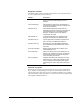
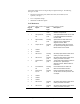
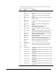
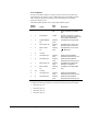
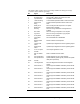
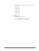
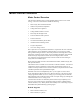
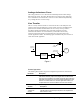
Table Of Contents
- Safety Symbol Legend
- Chapter 1 Overview
- Chapter 2 Faults and Troubleshooting
- Chapter 3 Paramters/Functions
- Introduction
- Diagnostic and Utility Functions
- Drive Configuration Functions
- General Setup Functions
- I/O Functions
- LAN Functions
- Motor Control Functions
- Protective Functions
- Custom User Faults
- DC Link Protection
- Ground Fault Protection (Fast)
- Hardware Fault Strings
- Heatsink Thermal Protection
- Line-Line Voltage Protection
- Motor Overtemperature Detection
- Phase Current Protection
- Timed Overcurrent Detection
- Transformer Overtemperature Detection
- Motor Ground Protection
- Phase Imbalance Monitor
- Line Monitor
- Phase Lock Loop
- Sequencer Functions
- Speed Reference Functions
- Speed/Torque Control Functions
- System Data Parameters
- Chapter 4 Wizards
- Introduction
- Introduction 4-1
- DAC Setup
- Drive Commissioning
- Drive Commissioning: Overview
- Drive Commissioning: Intelligent Part Number
- Drive Commissioning: Drive Units
- Drive Commissioning: AC Source Selection
- Drive Commissioning: Motor Nameplate Data
- Drive Commissioning: Motor Crossover Voltage
- Drive Commissioning: Motor Protection Class
- Drive Commissioning: Motor Poles
- Drive Commissioning: Motor Data Sheet
- Drive Commissioning: Motor Data Sheet - Equivalent Circuit Data
- Drive Commissioning: Motor Data Sheet - Flux Curve
- Drive Commissioning: Motor and Process Speed Referencing
- Drive Commissioning: Tachometer Support
- Drive Commissioning: Tachometer Pulses Per Revolution
- Drive Commissioning: Tachometer Loss Protection
- Drive Commissioning: Stopping Configuration
- Drive Commissioning: Flying Restart
- Drive Commissioning: X-Stop Configuration
- Drive Commissioning: X-Stop Ramp Time
- Drive Commissioning: Run Ready Permissive String
- Drive Commissioning: Starting and Stopping the Drive
- Drive Commissioning: Manual Reference
- Drive Commissioning: Maximum Speed References
- Drive Commissioning: Jog Speed Setpoints
- Drive Commissioning: Reference Ramp Bypass
- Drive Commissioning: Reference Ramp Mode
- Drive Commissioning: Reference Ramp Speed Independent Rates
- Drive Commissioning: Reference Ramp Speed Independent Rate Set Selection
- Drive Commissioning: Reference Ramp Programmed Acceleration Rates
- Drive Commissioning: Reference Ramp Programmed Acceleration Speeds
- Drive Commissioning: Reference Ramp Programmed Deceleration Rates
- Drive Commissioning: Reference Ramp Programmed Deceleration Speeds
- Drive Commissioning: DDI Increment and Decrement Rates (Local Mode)
- Drive Commissioning: Speed/Torque Regulator Configuration
- Drive Commissioning: Speed/Torque Regulator Modes
- Drive Commissioning: Torque Regulator Reference and Output
- Drive Commissioning: Torque with Speed Override Reference and Output
- Drive Commissioning: Torque with Speed Override Speed Error
- Drive Commissioning: Torque with Speed Override Stopping Behavior
- Drive Commissioning: Torque and Current Limits
- Drive Commissioning: Torque and Current Limits Uniform
- Drive Commissioning: Failed Calculation
- Drive Commissioning: Torque and Current Limit Selection
- Drive Commissioning: Normal Torque and Current Limits
- Drive Commissioning: Alternate Torque and Current Limits
- Drive Commissioning: Motoring Torque Limits
- Drive Commissioning: Generating Torque Limits
- Drive Commissioning: Current Limits
- Drive Commissioning: Power Dip Ride-Through
- Drive Commissioning: Parameter Calculation
- Drive Commissioning: Simulator Mode
- Drive Commissioning: Hardware Fault Strings in Simulator Mode
- Drive Commissioning: Simulator Mechanical Configuration
- Drive Commissioning: Exit Reminder
- Drive Commissioning: Conclusion
- Line Transfer Tuneup
- Motor Control Tuneup
- Panel Meter Setup
- Per Unit Setup
- Line Protection Setup
- Pulse Test
- Remaining Parameter Setup
- Simulator Setup
- Speed Regulator Tuneup
- Speed Regulator Tuneup: Model
- Speed Regulator Tuneup: System Inertia
- Speed Regulator Tuneup: Inertia Measurement Command
- Speed Regulator Tuneup: Speed Regulator Mode
- Speed Regulator Tuneup: Manual Regulator Tuneup
- Speed Regulator Tuneup: 1st Order Response
- Speed Regulator Tuneup: 2nd Order Response
- Speed Regulator Tuneup: 2nd Order Response with Stiffness Filter
- Speed Regulator Tuneup: Calculate Speed Regulator Gains Command
- Notes
- Chapter 5 Signal Mapping
- Appendix A Function Block Diagrams
- Index
- Reader Comments

3-38
•
••
•
Chapter 3 Paramters/Functions Innovation Series Medium Voltage GP Type - G Drives GEH-6385
The LAN watchdog function describes the set of mechanisms the drive uses to
determine the status of the connection between DSPX and the module immediately
“above” the drive in the LAN hierarchy. For Dual-Port RAM interfaces, such as that
used for an embedded ACLA controller and for a direct LAN interface, the watchdog
takes the form of a handshake protocol. In this handshake protocol, the drive
determines the presence of a minimum level of intelligence on the host on the LAN
side of the shared memory. For ISBus interfaces, such as that used by a remote or
embedded ACLA controller, the watchdog reflects the reception of ISBus frame
synchronization codes. The watchdog function’s immediate authority is limited to
alarms and status variables, although the status information does play a functional
role in the interface management. Note that the watchdog does not offer information
about the LAN connection’s status which may be supported beyond the immediate
interface to DSPX. In fact, many device networks offer no means of determining
basic network health.
The LAN heartbeat function is visible to the user. The heartbeat function uses
published signal map channels, and is available for use by the application. It provides
a means to “loop back” a signal between the drive and any level in the LAN
hierarchy so a higher-level controller can validate the entire connection pathway,
including the drive itself. Locally, the drive can be configured to trigger a trip or
alarm if the heartbeat reference signal fails to transition within a configurable period
of time. The heartbeat offers the most robust validation options from a system
perspective, although it offers the least information about the detected problem’s
location.
The System ISBus error alarm occurs when an ISBus fault is detected in the DSPX
control. The variable Sys ISBus error reg contains the bit-coded value of the last
ISBus fault detected; each bit indicates a particular ISBus fault seen by the control.
The variable Sys ISBus error cnt increments upon fault detection. When initializing
the interface, the user should expect the alarm to signal intermittently.
The Frame PLL not OK alarm occurs when phase-lock between the DSPX control
and the System ISBus or (local ACL) is not assured. Detection of the fault is enabled
when the parameter Network interface is configured to select an interface for which
synchronized operation is supported. This alarm indicates that data coherency is
compromised. Status of the Frame Phaselock Loop function can be observed via the
signals Frame PLL OK status, FPLL Phase error, and FPLL Freq Output.
LAN Signal Map
The following information describes the primary signal interface between the
Innovation Series Drive and the product application layer interface. The application
layer may consist of an embedded ACL card, a direct LAN interface card, or an
application-level ISBus serial bus.
The LAN Signal Map is a fixed signal map that defines dedicated registered
communication channels for specific signals. It is defined in terms of paired
reference and feedback pages that are the same size physically. The internal data
organization of the reference and feedback pages may differ. The standard
Innovation Series signal map page consists of eight 32-bit elements.