
- General Electric Computer Accessories User Manual
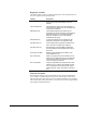
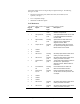
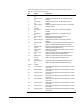
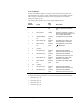
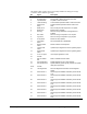
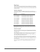
Table Of Contents
- Safety Symbol Legend
- Chapter 1 Overview
- Chapter 2 Faults and Troubleshooting
- Chapter 3 Paramters/Functions
- Introduction
- Diagnostic and Utility Functions
- Drive Configuration Functions
- General Setup Functions
- I/O Functions
- LAN Functions
- Motor Control Functions
- Protective Functions
- Custom User Faults
- DC Link Protection
- Ground Fault Protection (Fast)
- Hardware Fault Strings
- Heatsink Thermal Protection
- Line-Line Voltage Protection
- Motor Overtemperature Detection
- Phase Current Protection
- Timed Overcurrent Detection
- Transformer Overtemperature Detection
- Motor Ground Protection
- Phase Imbalance Monitor
- Line Monitor
- Phase Lock Loop
- Sequencer Functions
- Speed Reference Functions
- Speed/Torque Control Functions
- System Data Parameters
- Chapter 4 Wizards
- Introduction
- Introduction 4-1
- DAC Setup
- Drive Commissioning
- Drive Commissioning: Overview
- Drive Commissioning: Intelligent Part Number
- Drive Commissioning: Drive Units
- Drive Commissioning: AC Source Selection
- Drive Commissioning: Motor Nameplate Data
- Drive Commissioning: Motor Crossover Voltage
- Drive Commissioning: Motor Protection Class
- Drive Commissioning: Motor Poles
- Drive Commissioning: Motor Data Sheet
- Drive Commissioning: Motor Data Sheet - Equivalent Circuit Data
- Drive Commissioning: Motor Data Sheet - Flux Curve
- Drive Commissioning: Motor and Process Speed Referencing
- Drive Commissioning: Tachometer Support
- Drive Commissioning: Tachometer Pulses Per Revolution
- Drive Commissioning: Tachometer Loss Protection
- Drive Commissioning: Stopping Configuration
- Drive Commissioning: Flying Restart
- Drive Commissioning: X-Stop Configuration
- Drive Commissioning: X-Stop Ramp Time
- Drive Commissioning: Run Ready Permissive String
- Drive Commissioning: Starting and Stopping the Drive
- Drive Commissioning: Manual Reference
- Drive Commissioning: Maximum Speed References
- Drive Commissioning: Jog Speed Setpoints
- Drive Commissioning: Reference Ramp Bypass
- Drive Commissioning: Reference Ramp Mode
- Drive Commissioning: Reference Ramp Speed Independent Rates
- Drive Commissioning: Reference Ramp Speed Independent Rate Set Selection
- Drive Commissioning: Reference Ramp Programmed Acceleration Rates
- Drive Commissioning: Reference Ramp Programmed Acceleration Speeds
- Drive Commissioning: Reference Ramp Programmed Deceleration Rates
- Drive Commissioning: Reference Ramp Programmed Deceleration Speeds
- Drive Commissioning: DDI Increment and Decrement Rates (Local Mode)
- Drive Commissioning: Speed/Torque Regulator Configuration
- Drive Commissioning: Speed/Torque Regulator Modes
- Drive Commissioning: Torque Regulator Reference and Output
- Drive Commissioning: Torque with Speed Override Reference and Output
- Drive Commissioning: Torque with Speed Override Speed Error
- Drive Commissioning: Torque with Speed Override Stopping Behavior
- Drive Commissioning: Torque and Current Limits
- Drive Commissioning: Torque and Current Limits Uniform
- Drive Commissioning: Failed Calculation
- Drive Commissioning: Torque and Current Limit Selection
- Drive Commissioning: Normal Torque and Current Limits
- Drive Commissioning: Alternate Torque and Current Limits
- Drive Commissioning: Motoring Torque Limits
- Drive Commissioning: Generating Torque Limits
- Drive Commissioning: Current Limits
- Drive Commissioning: Power Dip Ride-Through
- Drive Commissioning: Parameter Calculation
- Drive Commissioning: Simulator Mode
- Drive Commissioning: Hardware Fault Strings in Simulator Mode
- Drive Commissioning: Simulator Mechanical Configuration
- Drive Commissioning: Exit Reminder
- Drive Commissioning: Conclusion
- Line Transfer Tuneup
- Motor Control Tuneup
- Panel Meter Setup
- Per Unit Setup
- Line Protection Setup
- Pulse Test
- Remaining Parameter Setup
- Simulator Setup
- Speed Regulator Tuneup
- Speed Regulator Tuneup: Model
- Speed Regulator Tuneup: System Inertia
- Speed Regulator Tuneup: Inertia Measurement Command
- Speed Regulator Tuneup: Speed Regulator Mode
- Speed Regulator Tuneup: Manual Regulator Tuneup
- Speed Regulator Tuneup: 1st Order Response
- Speed Regulator Tuneup: 2nd Order Response
- Speed Regulator Tuneup: 2nd Order Response with Stiffness Filter
- Speed Regulator Tuneup: Calculate Speed Regulator Gains Command
- Notes
- Chapter 5 Signal Mapping
- Appendix A Function Block Diagrams
- Index
- Reader Comments

3-42
•
••
•
Chapter 3 Paramters/Functions Innovation Series Medium Voltage GP Type - G Drives GEH-6385
The following table specifies the LAN Signal Map feedback bits that appear in Page
1, Element 1 of the feedback signal map.
Bit Signal Description
0 Heartbeat fbk, lan Heartbeat signal to validate LAN health.
1 No faults active No trip faults or alarms are active in the drive.
2 Trip fault active Trip fault is active in the drive.
3 Local fault string Local hardware permissive fault is active in the drive.
4
System fault
string
System hardware permissive fault is active in the
drive.
5 Ready to run Drive is ready and will respond to a run request.
6 Bridge is on Bridge power is enabled.
7 Running
Drive is running: References and regulators are
enabled.
8 Run active Drive is running in response to a run request.
9 Jog active Drive is running in response to a jog request.
10 X stop active Result of X stop requests.
11 Flux enable
status
Net commanded flux is established.
12 Reverse mode
active
Result of reverse mode requests.
13
Torque mode
active
Speed/Torque Regulator function is regulating torque.
14 Speed mode
active
Speed/Torque Regulator function is regulating speed.
15 In cur or trq limit Inner torque regulator is in limit.
16 Unused
17 MA cont enable
stat
Real or modeled contactor status.
18 Auto mode active Speed reference source is auto reference.
19 Zero speed active Speed feedback (Speed reg fbk) is below zero speed
level (Zero speed level).
20-22 Unused
23 Lan diag fbk bit 1 Drive has diagnostic information for the diagnostic
master.
24 GP lan fbk bit 1 General purpose feedback selected by GP lan fbk bit
1 sel.
25 GP lan fbk bit 2
General purpose feedback selected by GP lan fbk bit
2 sel.
26 GP lan fbk bit 3 General purpose feedback selected by GP lan fbk bit
3 sel.
27 GP lan fbk bit 4 General purpose feedback selected by GP lan fbk bit
4 sel.
28 GP lan fbk bit 5 General purpose feedback selected by GP lan fbk bit
5 sel.
29 GP lan fbk bit 6
General purpose feedback selected by GP lan fbk bit
6 sel.
30 GP lan fbk bit 7 General purpose feedback selected by GP lan fbk bit
7 sel.
31 GP lan fbk bit 8 General purpose feedback selected by GP lan fbk bit
8 sel.