g GE Consumer Home Services Training TECHNICAL SERVICE GUIDE Triton XL Dishwashers MODEL SERIES: EDW4000 EDW4060 GSD6200 GSD6300 GSD6600 GSD6660 GSD6700 PUB # 31-9085 PDW7300 PDW7700 PDW7800 PDW7880 09/01
! IMPORTANT SAFETY NOTICE The information in this service guide is intended for use by individuals possessing adequate backgrounds of electrical, electronic, and mechanical experience. Any attempt to repair a major appliance may result in personal injury and property damage. The manufacturer or seller cannot be responsible for the interpretation of this information, nor can it assume any liability in connection with its use. WARNING To avoid personal injury, disconnect power before servicing this product.
Table of Contents Table of Contents Introduction ......................................................................................................... 2 Nomenclature ...................................................................................................... 3 Control Panel Features5 Profile Models ................................................................................................. 4 GE Models ........................................................................................
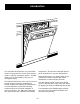
Introduction The new Triton XL Dishwashers are packed with features to get your dishes cleaner, pots and pans spotless, and keep your kitchen quieter... and with a power usage of 477 kWhr/yr, they have an “EnergyStar” rating. The Triton XL Dishwashers have 3 wash arms that provide complete coverage, eliminating prerinsing, soaking, and scrubbing. The ExtraCleanTM sensor incorporates a thermistor Auto Temp control and measures the water turbidity in 5 levels of cleanliness.
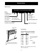
Nomenclature Model Number P D W 7 3 0 0 G 0 0 W W Brand P = Profile E = General Electric - NATM G = General Electric Product Type CD - Counter Top SD = Standard SM = Spacemaker RF = Retrofit Exterior Color BB = Black CC = Bisque SS = Stainless Steel WW = White DW = Dishwasher SC = Convertable SS = Compact (18 in.) HD = Home Depot Derivative Engineering Model Suffix Model Designator Designates features–the higher the number, the more features.
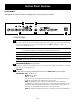
Control Panel Features Profile Models Throughout this manual, features and appearance may vary from your model. 1 6 TIME REMAINING 3 5 4 2 Control Settings 1 Status Indicator Lights The Status display tells you what’s happening while the dishwasher is in operation and may flash, indicating a malfunction (see page 86). The lights will come ON indicating the sequence of operation the dishwasher is in.
COOK Heavy 11.4 gal., 95 min. WARE Medium 10.0 gal., 71 min. Light 10.0 gal., 66 min. This cycle is meant for heavily soiled dishes or cookware with dried-on or baked-on soils. This cycle may not remove burned-on foods. Everyday dishes are safe to be used in this cycle. NORMAL WASH Heavy 9.9 gal., 74 min. Medium 7.0 gal., 61 min. Light 5.6 gal., 48 min. This cycle is for medium/heavily soiled dishes and glassware. SPEED CYCLE Heavy 9.3 gal., 36 min. Medium 7.2 gal., 36 min. Light 5.7 gal., 33 min.
DELAY HOURS You can delay the start of a wash cycle for up to 9 hours (on some models). Press the DELAY HOURS pad to choose the number of hours you want to delay the start of the cycle, then press START/RESET. The machine will count down and start automatically at the correct time. Pressing START/RESET a second time will cancel the DELAY START selection. NOTE: If you forget to fully close the door a reminder signal will beep until you do so.
2 ExtraClean™ Sensor Selections The light above the selected pad will be ON to indicate which ExtraClean™ Sensor Selection has been selected. ANTI-BACTERIA Heavy 10.0 gal., 93 min. Medium 8.6 gal., 90 min. Light 7.2 gal., 90 min. This cycle raises the water temperature in the final rinse to sanitize your dishware. The cycle length will vary depending on the temperature of your inlet water. NOTE: The Anti-Bacteria cycle is monitored for sanitization requirements.
LOCK You can lock the controls to prevent any selections from being made. Or you can lock the controls after you have started a cycle. Children cannot accidentally start dishwasher by touching pads with this option selected. To unlock the dishwasher controls, press and hold the HEATED DRY pad for 3 seconds. To lock the dishwasher, press and hold the HEATED DRY pad for 3 seconds. The light above the LOCK pad will turn off.
Component Locator Views Door View (Panel and Escutcheon Removed) Flapper (Active Vent) Vent Driver (Active Vent) Door Interlock Switch Control Module Detergent/ Rinse Agent Module Factory Test Cable Flood Switch Circulation Pump –9– House Electrical Supply Junction Box
Door View (Front Panel ONLY Removed) Active Vent Escutcheon Keypad Assembly Latch Handle Bottom View Circulation Pump Motor Flood Switch Control Module Junction Box FRONT FRONT Water Valve Factory Test Cable Connector Turbitity Sensor Drain Line Check Valve BACK BACK Drain Pump Heating Element Retaining Nuts High Drain Loop – 10 – Sump
Inside View Upper Spray Arm Middle Spray Arm Water Supply Connection Main Conduit Lower Spray Arm Heating Element Fine Filter Inlet Cover Hub Inside Door View Detergent/Rinse Module Detergent Compartment Vent (Active Vent) P0003687 – 11 –
Side View Drain Tube Assembly Fill Funnel Door Spring Fill Hose Water Valve Drain Line Check Valve P0003689 – 12 –
Dishwasher Components Flapper Door Components The door components are accessible by removing 3 Phillips screws from each side of inner door and 2 T20 torx screws from the bottom of the door. Carefully separate the inner door panel from the outer door panel. To access the active vent, flapper, and door interlock switch, the escutcheon keypad assembly must be removed.
Control Module 1 Screw 2 Tabs Removal 1. Remove the outer door panel (see Door Components). 2. Open the door and remove the 3 screws from the back on the right side of the escutcheon keypad assembly. 3. Remove 1 screw from the right side of the control module and slide the module out. 4. Unplug the connectors from the module. Installation P0003697 Note: The gray cable is a factory test cable (see photo) and may be removed when servicing control module. Factory Test Cable 1.
Stainless Steel Bowed Panel (On Some Models) Disassembly 1. Open the dishwasher door to the fully open (89 degrees open) position. 2. Remove 8 screws (4 screws per side) which hold the outer panel to the door assembly. Be careful not to remove the 2 screws which hold the escutcheon to the door assembly. Do not remove this screw from either side. 3. Slowly close the door. 4. Once the door is closed, remove the 2 screws that connect the bottom of the outer panel to the hinge arms. 5.
sure that the protruding ribs from the escutcheon fit inside the stainless steel front opening. Adjust the position of the outer panel up or down, left or right to center the panel with the escutcheon. 6. Once the panel is centered, install the 2 screws in the bottom of the panel to connect the stainless steel outer panel to the hinge arms. Recheck to make sure the escutcheon ribs are protruding through the panel opening. 7.
Bottom Door Seal Bottom Door Seal The bottom door seal is replaceable by removing the outer door panel (see Door Components). With the door closed, insert a flat-blade screwdriver under the bottom of the door into the channel and twist to break the bead. Open the door and pull the seal from the channel. To install the seal, snap the seal into the channel, working from one side of the door to the other, until the entire bead is complete and the seal slides freely in the channel.
L1 Output from J2-5 Dishwasher Doesn’t Drain DRAIN PUMP RX J2-5 M 30 WR DOOR INTERLOCK WX NO COM N Attempt to activate drain pump using service mode (refer to Service Mode chapter). YES NO Pump activate? Check for clogged: inlet cover sump drain pump drain pipe one-way check valve (in drain pipe) Is L1 voltage present at pump? Note: Perform this test with wiring connected and pump under load.
through the hub to the lower spray arm and to the main conduit. The main conduit supplies water to the middle and upper spray arms. Inlet Cover Caution: Use care to avoid breaking the clip on the hub when removing the main conduit from hub. Remove the lower wash arm and main conduit to gain access to the inlet cover and sump. Fine Filter, Sump Filter, and Sump The dishwasher must be removed from its installation to gain access to the sump.
No Water Circulation Attempt to activate circulation pump using service mode (refer to Service Mode chapter). YES NO Does pump activate? Check for clogged: hub (remove lower wash arm) inlet cover fine filter sump/sump filter Does the pump hum? YES Pump is stalled/clogged. Disconnect power and attempt to turn pump using cooling fins. Motor capacitor is open/ shorted. NO Important: Self tapping ground-wire screw on pump must be tightened securely. Check pump for open/ shorted motor winding.
during the drying cycle, drops to 700 W for gentler drying. HEATING ELEMENT Water inlet temperature must be at least 120 °F for proper drying. Low water inlet temperature will prevent proper convection air movement and increase drying time substantially. DOOR INTERLOCK WR WX NO COM HEATING ELEMENT VX J2-3 19.4-19.8 N J2-4 If the complaint is the dishes are not drying correctly, don’t overlook the rinse agent. A rinse agent will improve the water sheeting action and drying performance.
Replacement Screw To remove the turbidity sensor from the side of the sump, loosen the screw and slide the retaining clamp back. Remove turbidity sensor from the sump and unplug connector from the turbidity sensor. Turbidity sensor shown partially removed. Note: When installing the turbidity sensor, align the key on the sensor with the keyway on the sump. Keyway and Key Water Valve and Flood Switch The water valve is a 120 VAC (L1) solenoid valve that is switched on/off by the control module.
water level is low, check the following: Float Dome • Flood switch, flood switch float, and float stem - Flood switch should open when water level is approximately 1/4 in. above the base (bottom) of the float dome. • Resistance through the water valve solenoid coil - Check from yellow wire at flood switch to white/red wire at door interlock switch (Escutcheon keypad assembly must be removed, refer to Escutcheon Keypad Assembly section). • Clogged screen in water valve.
Flashing Display Lights The status display tells you what’s happening while the dishwasher is in operation and may flash, indicating a malfunction. The lights will come on indicating the sequence of operation the dishwasher is in. FLASHING DISPLAY LIGHTS Status Indicator Lights START/RESET CLEAN What It Means Cycle has been interrupted by pressing the START/RESET keypad. Light will quit flashing after the dishwasher automatically drains out the water. Unit has no water. Check the water supply.
Service Mode THIS DISHWASHER IS PROGRAMMED WITH A SERVICE MODE TO AID THE TECHNICIAN IN TROUBLESHOOTING THE DISHWASHER. EACH COMPONENT MAY BE CYCLED TO DETECT IF IT IS FUNCTIONING CORRECTLY. COMPONENTS ARE CYCLED BY PRESSING KEYPADS TO THE RIGHT OR LEFT OF THE START/RESET KEYPAD. DETERMINE WHICH TYPE OF CONTROL PANEL IS PRESENT (FLAT OR BOWED) AND THEN USE THE MATRIX BELOW TO DETERMINE HOW TO CYCLE EACH COMPONENT.
Factory Test Mode Factory test mode is the most accurate way to test the turbidity sensor circuit (circuit contains control module, wiring, and turbidity sensor). Factory test mode will test the thermistor (used for Automatic Temperature Control) that is contained in the turbidity sensor and will test the transmitter that is contained in the turbidity sensor. Entering Factory Test Mode module will beep continuously and the Lock LED will be illuminated.
Washability Complaints Hot Water – Ample supply of water at a minimum temperature of 120 °F is necessary. Do not use dishwasher soon after using clothes washer or filling bath tub. Float Dome Loading – Consult Owner’s Manual on loading procedures. Amount of Water – Make sure dishwasher is level. Check water level, allowing dishwasher to fill normally for first fill. The water level should be to the base (bottom) of the float dome.
Cycle Progression Chart TE MP NORMAL WASH (CLEAN) (DIRTY) 140 °F* GLASSES CYCLE 140 °F* 130 °F* CHINA CRYSTAL POTS & PANS 130 °F* ANTIBACTERIA 145 °F* RINSE ONLY 160 °F* - FO UR TH FI LL TH IR D FI LL SE CO ND FI LL FI RS T FI LL MA X 140 °F* SPEED CYCLE fill time 49 / 70 sec 49 / 70 sec 50 / 71sec 50 / 71sec fill quantity 1.4 gal 1.4 gal 1.43 gal 1.
Wiring Diagram WARNING: Power must be disconnected before servicing the appliance.
Parts List Door Note: The components shown in this drawing may differ from the components in your unit. Refer to the microfiche or GEA IPC for the component and part number for your unit.
Body Parts Note: The components shown in this drawing may differ from the components in your unit. Refer to the microfiche or GEA IPC for the component and part number for your unit.
Upper Rack Note: The components shown in this drawing may differ from the components in your unit. Refer to the microfiche or GEA IPC for the component and part number for your unit.
Lower Rack Note: The components shown in this drawing may differ from the components in your unit. Refer to the microfiche or GEA IPC for the component and part number for your unit.
Pumps and Filters Note: The components shown in this drawing may differ from the components in your unit. Refer to the microfiche or GEA IPC for the component and part number for your unit.
Note: The components shown in this drawing may differ from the components in your unit. Refer to the microfiche or GEA IPC for the component and part number for your unit.
Note: The components shown in this drawing may differ from the components in your unit. Refer to the microfiche or GEA IPC for the component and part number for your unit.
Note: The components shown in this drawing may differ from the components in your unit. Refer to the microfiche or GEA IPC for the component and part number for your unit.
Review 1. The incoming water temperature must be _________. 2. The dishwasher has a ______ year parts warranty. 6. The high drain loop, mounted on the side of the tub, can be removed if needed. The electronic module has a _____ year _________________ warranty. T or F 7. A blinking START/RESET keypad light indicates: 3. The dishwasher has a ______ year labor warranty. a. Sequence switch problem. b. Cycle was interrupted and dishwasher will drain and stop. 4.
Warranty Profile Models All warranty service provided by our Factory Service Centers, or an authorized Customer Care® technician. To schedule service, on-line, 24 hours a day, visit us at GEAppliances.com, or call 800.GE.CARES (800.432.2737). Staple your receipt here. Proof of the original purchase date is needed to obtain service under the warranty.
GE Models All warranty service provided by our Factory Service Centers, or an authorized Customer Care® technician. To schedule service, on-line, 24 hours a day, visit us at GEAppliances.com, or call 800.GE.CARES (800.432.2737). For The Period Of: One Year One Year Staple your receipt here. Proof of the original purchase date is needed to obtain service under the warranty.
Notes – 41 –
– 42 –