GE Consumer & Industrial Multilin EPM 6000 Multi-function Power Metering System Chapter 1: EPM 6000 Instruction Manual Software Revision: 4.5 Manual P/N: 1601-0215-A4 Manual Order Code: GEK-106558C Copyright © 2007 GE Multilin RE ISO9001:2000 G EM Canada L6E 1B3 I N 215 Anderson Avenue, Markham, Ontario U LT I L GE Multilin's Quality Management System is registered to ISO9001:2000 Tel: (905) 294-6222 Fax: (905) 201-2098 Internet: http://www.GEmultilin.
Table of Contents 1: OVERVIEW INTRODUCTION ................................................................................................................................ 1-1 DESCRIPTION ........................................................................................................................ 1-1 HIGHLIGHTS ......................................................................................................................... 1-1 FEATURES ....................................................
INSTALLATION CONSIDERATIONS ....................................................................................... 3-5 CT LEADS TERMINATED TO METER ................................................................................... 3-6 CT LEADS PASS-THROUGH (NO METER TERMINATION) ................................................ 3-6 QUICK CONNECT CRIMP CT TERMINATIONS ................................................................... 3-7 VOLTAGE AND POWER SUPPLY CONNECTIONS ................................
DNP IMPLEMENTATION ................................................................................................................. 5-13 OVERVIEW ............................................................................................................................ 5-13 DATA LINK LAYER ................................................................................................................ 5-13 TRANSPORT LAYER .....................................................................................
TOC–4 EPM 6000 MULTI-FUNCTION POWER METERING SYSTEM – USER GUIDE
GE Consumer & Industrial Multilin EPM 6000 Multi-function Power Metering System Chapter 1: Overview Overview 1.1 Introduction 1.1.1 Description The EPM 6000 is a multifunction power meter designed to be used in electrical substations, panel boards and as a power meter for OEM equipment. The unit provides multifunction measurement of electrical parameters. The unit is designed with advanced measurement capabilities, allowing it to achieve high performance accuracy. The EPM 6000 is specified as a 0.
CHAPTER 1: OVERVIEW FIGURE 1–1: EPM 6000 Highlights 1–2 EPM 6000 MULTI-FUNCTION POWER METERING SYSTEM – USER GUIDE
CHAPTER 1: OVERVIEW 1.2 Features 1.2.1 Universal Voltage Inputs Voltage Inputs allow measurement to 416 V line-to-neutral and 721 V line-to-line. This insures proper meter safety when wiring directly to high voltage systems. One unit will perform to specification on 69 V, 120 V, 230 V, 277 V, and 347 V systems. 1.2.2 Current Inputs The EPM 6000 current inputs use a unique dual input method.
CHAPTER 1: OVERVIEW Utility demand features can be used to calculate kW, kvar, kVA and PF readings. All other parameters offer maximum and minimum capability over the user-selectable averaging period. Voltage provides an instantaneous maximum and minimum reading which displays the highest surge and lowest sag seen by the meter. 1.2.4 Measured Values The EPM 6000 provides the following measured values all in real time and some additionally as average, maximum, and minimum values.
CHAPTER 1: OVERVIEW 1.3 Ordering 1.3.1 Order Codes The order codes for the EPM 6000 are indicated below.
CHAPTER 1: OVERVIEW 1.4 Specifications 1.4.1 Inputs/Outputs POWER SUPPLY Range:..................................................................D2 Option: Universal, 90 to 265 V AC at 50/60Hz, or 100 to 370 V DC D Option: 18 to 60 V DC Power consumption:.....................................5 VA, 3.5 W VOLTAGE INPUTS (MEASUREMENT CATEGORY III) Range:..................................................................Universal, Auto-ranging up to 416 V AC L-N, 721 V AC L-L Supported hookups:...............
CHAPTER 1: OVERVIEW ACCURACY Measured Parameters Display Range Accuracy Voltage L-N 0 to 9999 kV or scalable 0.1% of reading Voltage L-L 0 to 9999 V or kV scalable 0.1% of reading Current 0 to 9999 A or kA 0.1% of reading +/– Watts 0 to 9999 W, kW, or MW 0.2% of reading +/– Wh 5 to 8 digits (programmable) 0.2% of reading +/– vars 0 to 9999 vars, kvars, Mvars 0.2% of reading +/– varh 5 to 8 digits (programmable) 0.2% of reading VA 0 to 9999 VA, kVA, MVA 0.
CHAPTER 1: OVERVIEW 1.4.6 Approvals TYPE TESTING IEC 687 (0.2% accuracy) ANSI C12.20 (0.2% accuracy) ANSI (IEEE) C37.90.1: ....................................Surge Withstand ANSI C62.41 (burst) IEC 1999-4-2: ...................................................ESD IEC 1000-4-3: ...................................................Radiated Immunity IEC 1000-4-4: ...................................................Fast Transient IEC 1000-4-5: ...................................................
GE Consumer & Industrial Multilin EPM 6000 Multi-function Power Metering System Chapter 2: Electrical Background Electrical Background 2.1 Three-Phase Power Measurement 2.1.1 Description This introduction to three-phase power and power measurement is intended to provide only a brief overview of the subject.
CHAPTER 2: ELECTRICAL BACKGROUND 2.2 Three-Phase System Configurations 2.2.1 Description Three-phase power is most commonly used in situations where large amounts of power will be used because it is a more effective way to transmit the power and because it provides a smoother delivery of power to the end load. There are two commonly used connections for three-phase power, a wye connection or a delta connection. Each connection has several different manifestations in actual use.
CHAPTER 2: ELECTRICAL BACKGROUND Vcn Ic Van Ia Ib Vbn FIGURE 2–2: Three-Phase Voltage and Current Phasors for Wye Winding The phasor diagram shows the 120° angular separation between the phase voltages. The phase-to-phase voltage in a balanced three-phase wye system is 1.732 times the phaseto-neutral voltage. The center point of the wye is tied together and is typically grounded. The following table indicates the common voltages used in the United States for wyeconnected systems.
CHAPTER 2: ELECTRICAL BACKGROUND 2.2.3 Delta Connection Delta connected services may be fed with either three wires or four wires. In a three-phase delta service the load windings are connected from phase-to-phase rather than from phase-to-ground. The following figure shows the physical load connections for a delta service. Ia A Iab Vab Vca Ib B Vbc Ica Ibc Ic C FIGURE 2–3: Three-Phase Delta Winding Relationship In this example of a delta service, three wires will transmit the power to the load.
CHAPTER 2: ELECTRICAL BACKGROUND Another common delta connection is the four-wire, grounded delta used for lighting loads. In this connection the center point of one winding is grounded. On a 120/240 volt, fourwire, grounded delta service the phase-to-ground voltage would be 120 volts on two phases and 208 volts on the third phase. The phasor diagram for the voltages in a threephase, four-wire delta system is shown below.
CHAPTER 2: ELECTRICAL BACKGROUND In a three-phase, four-wire wye system it is necessary to use three elements. Three voltage coils are connected between the three phases and the common neutral conductor. A current coil is required in each of the three phases. In modern digital meters, Blondell's Theorem is still applied to obtain proper metering. The difference in modern meters is that the digital meter measures each phase voltage and current and calculates the single-phase power for each phase.
CHAPTER 2: ELECTRICAL BACKGROUND If we measure the currents in wires A, B and C, we then know the current in wire N by Kirchhoff's Law and it is not necessary to measure it. This fact leads us to the conclusion of Blondell's Theorem that we only need to measure the power in three of the four wires if they are connected by a common node. In the circuit of Figure 1.6 we must measure the power flow in three wires. This will require three voltage coils and three current coils (a three element meter).
CHAPTER 2: ELECTRICAL BACKGROUND 2.3 Power, Energy, and Demand 2.3.1 Description It is quite common to exchange power, energy, and demand without differentiating between the three. Because this practice can lead to confusion, the differences between these three measurements will be discussed. 2.3.2 Power Power is an instantaneous reading. The power reading provided by a meter is the present flow of watts. Power is measured immediately just like current.
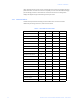
CHAPTER 2: ELECTRICAL BACKGROUND 80 70 kilowatts 60 50 40 30 20 10 0 1 2 3 4 5 6 7 8 9 10 11 12 13 14 15 Time (minutes) FIGURE 2–7: Power Use Over Time The data in the above figure is reproduced in the following table to illustrate the calculation of energy.
CHAPTER 2: ELECTRICAL BACKGROUND Table 2–2: Power and Energy Relationship Over Time Time Interval Power Energy Accumulated Energy 1 minute 30 kW 0.50 kWh 0.50 kWh 2 minutes 50 kW 0.83 kWh 1.33 kWh 3 minutes 40 kW 0.67 kWh 2.00 kWh 4 minutes 55 kW 0.92 kWh 2.92 kWh 5 minutes 60 kW 1.00 kWh 3.92 kWh 6 minutes 60 kW 1.00 kWh 4.92 kWh 7 minutes 70 kW 1.17 kWh 6.09 kWh 8 minutes 70 kW 1.17 kWh 7.26 kWh 9 minutes 60 kW 1.00 kWh 8.26 kWh 10 minutes 70 kW 1.17 kWh 9.
CHAPTER 2: ELECTRICAL BACKGROUND The following figure illustrates another example of energy and demand. In this case, each bar represents the energy consumed in a 15-minute interval. The energy use in each interval typically falls between 50 and 70 kWh. However, during two intervals the energy rises sharply and peaks at 100 kWh in interval #7. This peak of usage will result in setting a high demand reading. For each interval shown the demand value would be four times the indicated energy reading.
CHAPTER 2: ELECTRICAL BACKGROUND 2.4 Reactive Energy and Power Factor 2.4.1 Real, Reactive, and Apparent Power The real power and energy measurements discussed in the previous section relate to the quantities that are most used in electrical systems. But it is often not sufficient to only measure real power and energy. Reactive power is a critical component of the total power picture because almost all real-life applications have an impact on reactive power.
CHAPTER 2: ELECTRICAL BACKGROUND So keeping the var content low allows a line to carry its full capacity of watts. In order to encourage customers to keep VAR requirements low, most utilities impose a penalty if the var content of the load rises above a specified value. 2.4.2 Power Factor A common method of measuring reactive power requirements is power factor. Power factor can be defined in two different ways.
CHAPTER 2: ELECTRICAL BACKGROUND 2.5 Harmonic Distortion 2.5.1 Harmonics of a Non-Sinusoidal Waveform Harmonic distortion is primarily the result of high concentrations of non-linear loads. Devices such as computer power supplies, variable speed drives and fluorescent light ballasts make current demands that do not match the sinusoidal waveform of AC electricity. As a result, the current waveform feeding these loads is periodic but not sinusoidal.
CHAPTER 2: ELECTRICAL BACKGROUND frequency waveforms. These higher frequency waveforms are referred to as harmonics. The following figure shows the content of the harmonic frequencies that comprise one cycle of the distorted portion of the above waveform. 250 200 Current (amps) 150 100 50 t 0 a -50 -100 -150 -200 -250 FIGURE 2–12: Harmonics for Distorted Current Waveform The waveforms above provide an indication of the impact of combining multiple harmonic frequencies together.
CHAPTER 2: ELECTRICAL BACKGROUND accuracy; at frequencies above about 1200 Hz they pass almost no information. So when instrument transformers are used, they effectively filter out higher frequency harmonic distortion making it impossible to see. However, when monitors can be connected directly to the measured circuit (such as direct connection to 480 V bus) the user may often see higher order harmonic distortion.
CHAPTER 2: ELECTRICAL BACKGROUND 2.6 Power Quality 2.6.1 Description Power quality can mean several different things. The terms power quality and power quality problem have been applied to all types of conditions. A simple definition of power quality problem is any voltage, current or frequency deviation that results in misoperation or failure of customer equipment or systems.
CHAPTER 2: ELECTRICAL BACKGROUND 2–18 EPM 6000 MULTI-FUNCTION POWER METERING SYSTEM – USER GUIDE
GE Consumer & Industrial Multilin EPM 6000 Multi-function Power Metering System Chapter 3: Installation Installation 3.1 Mechanical Installation 3.1.1 Dimensions The EPM 6000 meter can be installed using a standard ANSI C39.1 (4" round) or an IEC 92 mm DIN (square) form. In new installations, simply use existing DIN or ANSI punches. For existing panels, pull out old analog meters and replace with the EPM 6000. The various models use the same installation.
CHAPTER 3: INSTALLATION FIGURE 3–2: ANSI and DIN Mounting Panel Cutouts 3.1.2 ANSI Installation Steps Mount the meter in a dry location free from dirt and corrosive substances. The meter is designed to withstand harsh environmental conditions (see the Environmental specifications in Chapter 2 for additional details). Use the following steps to install the meter: Z Insert the four threaded rods by hand into the back of the meter. Twist until secure.
CHAPTER 3: INSTALLATION NEMA12 mounting gasket threaded rods lock washer and nut FIGURE 3–3: ANSI Mounting Procedure 3.1.3 DIN Installation Steps Mount the meter in a dry location free from dirt and corrosive substances. The meter is designed to withstand harsh environmental conditions (see the Environmental specifications in Chapter 2 for additional details). Use the following steps to install the meter: Z Slide the meter with NEMA 12 mounting gasket into panel.
CHAPTER 3: INSTALLATION Z From back of the panel, slide 2 DIN mounting brackets into the grooves on the top and bottom of the meter housing, then snap into place. Z Secure meter to panel with a lock washer and #8 screw through each of the two mounting brackets. Tighten with a #2 Phillips screwdriver – do not overtighten.
CHAPTER 3: INSTALLATION 3.2 Electrical Installation 3.2.1 Installation Considerations Installation of the EPM 6000 Power Metering System must be performed by only qualified personnel who follow standard safety precautions during all procedures. Those personnel should have appropriate training and experience with high voltage devices. Appropriate safety gloves, safety glasses and protective clothing is recommended.
CHAPTER 3: INSTALLATION 3.2.2 CT Leads Terminated to Meter The EPM 6000 is designed to have current inputs wired in one of three ways. The figure below shows the most typical connection, where CT Leads are terminated to the meter at the current gills. This connection uses nickel-plated brass studs (current gills) with screws at each end. This connection allows the CT wires to be terminated using either an “O” or a “U” lug. Tighten the screws with a #2 Phillips screwdriver.
CHAPTER 3: INSTALLATION CT wire passing through the meter Current gills removed FIGURE 3–6: Pass-Through Wire Electrical Connection 3.2.4 Quick Connect Crimp CT Terminations For quick termination or for portable applications, a quick connect crimp CT connection can also be used. Crimp CT terminations FIGURE 3–7: Quick Connect Electrical Connection 3.2.5 Voltage and Power Supply Connections Voltage Inputs are connected to the back of the unit via a optional wire connectors.
CHAPTER 3: INSTALLATION Power supply inputs RS485 outputs (do not place voltage on these terminals!) Voltage inputs FIGURE 3–8: Voltage Connection 3.2.6 Ground Connections The EPM 6000 ground terminals ( ) should be connected directly to the installation's protective earth ground. Use 2.5 mm wire for this connection. GE recommends the use of fuses on each of the sense voltages and on the control power, even though the wiring diagrams in this chapter do not show them. • Use a 0.
CHAPTER 3: INSTALLATION 3.3 Wiring Diagrams 3.3.1 Description Choose the diagram that best suits your application and maintains the CT polarity. 1. Three-phase, four-wire system Wye with direct voltage, 3 element. 2. Three-phase, four-wire system Wye with direct voltage, 2.5 element. 3. Three-phase, four-wire Wye with PTs, 3 element. 4. Three-phase, four-wire Wye with PTs, 2.5 element. 5. Three-phase, three-wire Delta with direct voltage. 6. Three-phase, three-wire Delta with PTs. 7.
CHAPTER 3: INSTALLATION 3.3.2 Wye, 4-Wire with no PTs and 3 CTs, 3 Element For this wiring type, select 3 EL WYE (3-element Wye) in the meter programming setup.
CHAPTER 3: INSTALLATION 3.3.3 Wye, 4-Wire with no PTs and 3 CTs, 2.5 Element For this wiring type, select 2.5EL WYE (2.5-element Wye) in the meter programming setup. FIGURE 3–10: 4-Wire Wye with no PTs and 3 CTs, 2.
CHAPTER 3: INSTALLATION 3.3.4 Wye, 4-Wire with 3 PTs and 3 CTs, 3 Element For this wiring type, select 3 EL WYE (3-element Wye) in the meter programming setup.
CHAPTER 3: INSTALLATION 3.3.5 Wye, 4-Wire with 2 PTs and 3 CTs, 2.5 Element For this wiring type, select 2.5EL WYE (2.5-element Wye) in the meter programming setup. FIGURE 3–12: 4-Wire Wye with 2 PTs and 3 CTs, 2.
CHAPTER 3: INSTALLATION 3.3.6 Delta, 3-Wire with no PTs and 2 CTs For this wiring type, select 2 Ct dEL (2 CT Delta) in the meter programming setup.
CHAPTER 3: INSTALLATION 3.3.7 Delta, 3-Wire with 2 PTs and 2 CTs For this wiring type, select 2 Ct dEL (2 CT Delta) in the meter programming setup.
CHAPTER 3: INSTALLATION 3.3.8 Current-Only Measurement (Three-Phase) For this wiring type, select 3 EL WYE (3 Element Wye) in the meter programming setup. Note 3–16 Even if the meter is used only for current measurement, the unit requires a AN volts reference. Please ensure that the voltage input is attached to the meter. AC control power can be used to provide the reference signal.
CHAPTER 3: INSTALLATION 3.3.9 Current-Only Measurement (Dual-Phase) For this wiring type, select 3 EL WYE (3 Element Wye) in the meter programming setup. Note Even if the meter is used only for current measurement, the unit requires a AN volts reference. Please ensure that the voltage input is attached to the meter. AC control power can be used to provide the reference signal.
CHAPTER 3: INSTALLATION 3.3.10 Current-Only Measurement (Single-Phase) For this wiring type, select 3 EL WYE (3 Element Wye) in the meter programming setup. Note 3–18 Even if the meter is used only for current measurement, the unit requires a AN volts reference. Please ensure that the voltage input is attached to the meter. AC control power can be used to provide the reference signal.
CHAPTER 3: INSTALLATION 3.4 Communications Setup 3.4.1 Description The EPM 6000 Power Metering System provides two independent communication ports. The first port, COM1, is an optical IrDA port. The second port, COM2, provides RS485 communication via the Modbus protocol. 3.4.2 IrDA COM1 Port The COM1 IrDA port is located on the meter faceplate. The IrDA port allows the unit to be set up and programmed using a remote laptop without the need for a communication cable.
CHAPTER 3: INSTALLATION FIGURE 3–16: RS485 Communications Installation The EPM 6000 COM2 port can be programmed through the faceplate or with software. The standard RS485 port settings are: Address: 001 to 247 Baud rate: 9.6, 19.2, 38.4, or 57.6 kbps Protocol: Modbus RTU, Modbus ASCII, or DNP 3.
GE Consumer & Industrial Multilin EPM 6000 Multi-function Power Metering System Chapter 4: Using the Meter Using the Meter 4.1 Front Panel Interface 4.1.1 Description The EPM 6000 Power Metering System can be configured and a variety of functions can be accomplished simply by using the elements and the buttons on the meter faceplate. This chapter will review front panel navigation. Complete navigation maps can be found in Navigation Maps on page 6–1. 4.1.
CHAPTER 4: USING THE METER Parameter designator Reading type indicator IRDA communications port Watt-hour pulse % of Load Bar FIGURE 4–1: EPM 6000 Faceplate Elements 4.1.
CHAPTER 4: USING THE METER MENU button ENTER button DOWN button RIGHT button FIGURE 4–2: EPM 6000 Faceplate Buttons 4.1.4 Percentage of Load Bar The 10-segment LED bar graph at the bottom of the EPM 6000 front panel provides a graphic representation of current. The segments illuminate according to the load shown in the table below. When the load is greater than 120% of full-load, all segments flash “ON” for 1.5 seconds and “OFF” for 0.5 seconds.
CHAPTER 4: USING THE METER 4.1.5 Watt-Hour Accuracy Testing (Verification) To be certified for revenue metering, power providers and utility companies have to verify that the billing energy meter will perform to the stated accuracy. To confirm the meter's performance and calibration, power providers use field test standards to ensure that the unit's energy measurements are correct.
CHAPTER 4: USING THE METER 4.2 Configuring the Meter via the Front Panel 4.2.1 Overview The EPM 6000 front panel can be used to configure the meter. The EPM 6000 has three modes: operating mode (default), IrDA reset mode, and configuration mode. The MENU, ENTER, DOWN and RIGHT buttons navigate through the modes and navigate through all the screens in each mode. A typical setup will be demonstrated in this section; other settings are possible.
CHAPTER 4: USING THE METER 4.2.3 Main Menu The following procedure describes how the navigate the main menu. Z Push the MENU button from any of the auto-scrolling readings to display the main menu screens. The string for reset mode (rSt) will be blinking in the “A” Screen. Z Press the DOWN key to scroll the menu and display the configuration mode string (CFG) in the “A” screen. Z Press the DOWN key again to scroll the menu and display the operating mode string in the “A” screen.
CHAPTER 4: USING THE METER Z Press the RIGHT button to display the rSt ALL? YES message. Resetting the maximum and minimum value requires entry of a four-digit password, if enabled in software. Z Press ENTER to display the password screen. If password is enabled in the software, the screen displays the PASS message in the “A” screen and 4 dashes in the “B” screen, with the left-most digit flashing. Z Using the DOWN button, select 0 to 9 for the flashing digit.
CHAPTER 4: USING THE METER If an incorrect password has been entered, the PASS ---- FAIL message appears and the screen returns to the rSt ALL? YES message.
CHAPTER 4: USING THE METER 4.3 Changing Settings in Configuration Mode 4.3.1 Description The following procedure describes how the navigate the configuration mode menu. Z Press the MENU Button from any of the auto-scrolling readings. Z Press DOWN to display the configuration mode (CFG) in the “A” screen. w Press ENTER to scroll through the configuration parameters, starting at the SCrL Ct Pt screen. Z Push the DOWN Button to scroll all the parameters: scroll, CT, PT, connection (Cnct) and port.
CHAPTER 4: USING THE METER When in scroll mode, the unit scrolls each parameter for 7 seconds on and 1 second off. The meter can be configured through software to only display selected screens. In this case, it will only scroll the selected displays. Z Push ENTER to select YES or no. Z Scroll to the CT parameters screen. 4.3.3 Programming the Configuration Mode Screens Use the following procedure to program the screen for configuration mode.
CHAPTER 4: USING THE METER The Stor ALL donE message will appear and the meter will reset. 4.3.4 Configuring the CT Setting Use the following procedure to program the CT setting. Z Push the DOWN Button to scroll through the configuration mode parameters. Press ENTER when Ct is the active parameter (i.e. it is in the “A” screen and flashing). This will display the and the Ct-n (CT numerator) screen. Z Press ENTER again to change to display the Ct-d (CT denominator) screen.
CHAPTER 4: USING THE METER Z Press ENTER again to select the to Ct-S (CT scaling) value. The Ct-S value can be “1”, “10”, or “100”. Refer to Programming the Configuration Mode Screens on page 4–10 for instructions on changing values. The value for amps is a product of the Ct-n and the Ct-S values.
CHAPTER 4: USING THE METER This will display the and the Pt-n (PT numerator) screen. Z Press ENTER again to change to display the Pt-d (PT denominator) screen. Z Press ENTER again to select the to Pt-S (PT scaling) value. The Pt-S value can be “1”, “10”, or “100”. Refer to Programming the Configuration Mode Screens on page 4–10 for instructions on changing values.
CHAPTER 4: USING THE METER Z Push the DOWN Button to scroll through the configuration mode parameters. Z Press ENTER when Cnct is the active parameter (i.e. it is in the “A” screen and flashing). This will display the Cnct (connection) screen. The possible connection configurations are 3-element Wye (3 EL WYE), 2.5-element Wye (2.5EL WYE), and 2 CT Delta (2 Ct deL), as shown below. 3-Element Wye 2.5-Element Wye 2 CT Delta Z Press ENTER to scroll through the other CFG parameters.
CHAPTER 4: USING THE METER Z Select “rtU” for Modbus RTU, “ASCI” for Modbus ASCII, and “dnP” for the DNP 3.0 protocol. • The first POrt screen is meter address (Adr). The current address appears on the screen. Z Select three-digit number for the address. Refer to Programming the Configuration Mode Screens on page 4– 10 for details on changing values. Address 005 • The next POrt screen is the baud rate (bAUd). The current baud rate is displayed on the “B” screen.
CHAPTER 4: USING THE METER Z Press ENTER to scroll through the other CFG parameters. Z Press DOWN or RIGHT to display the password screen (see Reset Mode and Password Entry on page 4–6 for details). Z Press MENU to return to the main configuration menu.
CHAPTER 4: USING THE METER 4.4 Operating Mode 4.4.1 Description Operating mode is the EPM 6000 meter’s default mode. If scrolling is enabled, the meter automatically scrolls through these parameter screens after startup. The screen changes every 7 seconds. Scrolling is suspended for 3 minutes after any button is pressed. Push the DOWN button to scroll all the parameters in operating mode. The active parameter has the indicator light next to it on the right face of the meter.
CHAPTER 4: USING THE METER 4–18 EPM 6000 MULTI-FUNCTION POWER METERING SYSTEM – USER GUIDE
GE Consumer & Industrial Multilin EPM 6000 Multi-function Power Metering System Chapter 5: Communications Communications 5.1 Modbus Communications 5.1.1 Memory Map Description The Modbus memory map is divided into four primary sections: 1. Fixed data registers: addresses 0001 to 0021. 2. Meter data registers: addresses 1000 to 5003. The meter data registers read as “0” until the first readings are available or if the meter is not in operating mode.
CHAPTER 5: COMMUNICATIONS HEX ADDRESS DESCRIPTION1 UNITS OR RESOLUTION RANGE6 FORMAT COMMENTS # REG FIXED DATA SECTION Identification Block read-only 0000 - 0007 Meter Name ASCII 16 char none 0008 - 000F Meter Serial Number ASCII 16 char none 0010 - 0010 Meter Type UINT16 bit-mapped -------t -----vvv 0011 - 0012 Firmware Version ASCII 4 char none 0013 - 0013 Map Version UINT16 0 to 65535 none 0014 - 0014 Meter Configuration UINT16 bit-mapped -------- --ffffff UI
CHAPTER 5: COMMUNICATIONS HEX ADDRESS DESCRIPTION1 UNITS OR RESOLUTION RANGE6 FORMAT COMMENTS 0459 - 045A VAR-hours, Total SINT32 0 to 99999999 VARh per energy format 045B - 045C VA-hours, Total SINT32 0 to 99999999 VAh per energy format * see note 10 Block Size: Primary Demand Block (IEEE Floating Point) # REG 2 2 18 read-only - 07D0 Amps A, Average FLOAT 0 to 9999 M amps 07D1 - 07D2 Amps B, Average FLOAT 0 to 9999 M amps 07D3 - 07D4 Amps C, Average Positive Watts, 3-Ph, 07D5
CHAPTER 5: COMMUNICATIONS HEX ADDRESS 0C2F - 0C30 0C31 - 0C32 0C33 - 0C34 0C35 - 0C36 0C37 - 0C38 0C39 - 0C3A 0C3B - 0C3C DESCRIPTION1 FORMAT Positive VARs, 3-Ph, FLOAT Maximum Avg Demand Negative Watts, 3-Ph, FLOAT Maximum Avg Demand Negative VARs, 3-Ph, FLOAT Maximum Avg Demand VAs, 3-Ph, Maximum Avg FLOAT Demand Positive Power Factor, 3Ph, Maximum Avg FLOAT Demand Negative Power Factor, 3Ph, Maximum Avg FLOAT Demand Frequency, Maximum FLOAT UNITS OR RESOLUTION RANGE6 COMMENTS 0 to +9
CHAPTER 5: COMMUNICATIONS HEX ADDRESS DESCRIPTION1 FORMAT RANGE6 UNITS OR RESOLUTION COMMENTS Status Block read-only 1387 - 1387 Meter Status UINT16 bit-mapped --exnpch ssssssss exnpch = EEPROM block OK flags (e=energy, x=max, n=min, p=programmable settings, c=calibration, h=header), ssssssss = state (1=Run, 2=Limp, 10=Prog Set Update via buttons, 11=Prog Set Update via IrDA, 12=Prog Set Update via COM2) 1388 - 1388 Limits Status7 UINT16 bit-mapped 87654321 87654321 high byte is setpt
CHAPTER 5: COMMUNICATIONS HEX ADDRESS RANGE6 FORMAT UNITS OR RESOLUTION COMMENTS - 7532 PT denominator UINT16 1 to 9999 none 7533 - 7533 PT multiplier & hookup UINT16 bit-mapped mmmmmmmm MMMMhhhh MMMMmmmmmmmm is PT multiplier (1, 10, 100, 1000), hhhh is hookup enumeration (0 = 3 element wye[9S], 1 = delta 2 CTs[5S], 3 = 2.
CHAPTER 5: COMMUNICATIONS HEX ADDRESS DESCRIPTION1 7550 - 7554 Limit #2 SINT16 7555 - 7559 Limit #3 SINT16 755A - 755E Limit #4 SINT16 755F - 7563 Limit #5 SINT16 7564 - 7568 Limit #6 SINT16 7569 - 756D Limit #7 SINT16 756E - 7572 SINT16 Limit #8 UNITS OR RESOLUTION RANGE6 FORMAT same as Limit #1 same as Limit #1 COMMENTS same as Limit #1 Block Size: # REG 5 5 5 5 5 5 5 68 SECONDARY READINGS SECTION Secondary Block read-only except as noted 9C40 - 9C40 System Sanit
CHAPTER 5: COMMUNICATIONS 2. Meter Data Section items read as 0 until first readings are available or if the meter is not in operating mode. Writes to these registers will be accepted but won't actually change the register. 3. Register valid only in programmable settings update mode. In other modes these registers read as 0 and return an illegal data address exception if a write is attempted. 4. Meter command registers always read as 0. They may be written only when the meter is in a suitable mode.
CHAPTER 5: COMMUNICATIONS 14. All 3 voltage angles are measured for Wye and Delta hookups. For 2.5 Element, Vac is measured and Vab & Vbc are calculated. If a voltage phase is missing, the two voltage angles in which it participates are set to zero. A and C phase current angles are measured for all hookups. B phase current angle is measured for Wye and is zero for other hookups. If a voltage phase is missing, its current angle is zero. 5.1.
CHAPTER 5: COMMUNICATIONS 5.2 DNP Point Mapping 5.2.1 DNP Point Maps The DNP point mappings (DNP-11 to DNP-22) for the EPM 6000 Power Metering System shows the client-server relationship in GE Multilin’s use of the DNP protocol. The notes are listed after the table.
CHAPTER 5: COMMUNICATIONS Table 5–1: DNP Point Mapping (Sheet 2 of 2) Object 30 Var 5 Point Description Format Range/units Multiplier 15 Maximum average positive three-phase real power demand SINT16 –32768 to +32767 W (4500/32768) 16 Maximum average positive three-phase reactive power demand SINT16 –32768 to +32767 var (4500/32768) 17 Maximum average negative three-phase real power demand SINT16 –32768 to +32767 W (4500/32768) 18 Maximum average negative three-phase reactive power
CHAPTER 5: COMMUNICATIONS 5.2.2 DNP Point Map Notes 1. Responds to Function 5 (direct operate), Qualifier Code 7 or 8, Control Code 3, Count 0, On 1 ms, Off 0 ms ONLY. 2. Responds to Function 6 (direct operate - no acknowledge), Qualifier Code 7, Control Code 3, Count 0, On 1 ms, Off 0 ms ONLY. 3. The multiplier = 10(n–d), where n and d are derived from the energy format. n = 0, 3, or 6 per energy format scale and d = number of decimal places. 4. Example: If energy format = 7.
CHAPTER 5: COMMUNICATIONS 5.3 DNP Implementation 5.3.1 Overview The EPM 6000 meter is capable of using RS485 as the physical layer. This is accomplished by connecting a PC to the meter with the RS485 connection on the back face. RS485 provides multi-drop network communication capabilities. Multiple meters may be placed on the same bus, allowing for a master device to communicate with any of the other devices.
CHAPTER 5: COMMUNICATIONS 5.3.4 Application Layer The application layer contains a header (request or response header, depending on direction) and data. Application headers contain the application control field and the function code. For the application control field, multiple-fragment messages are not allowed for EPM 6000. Each application header should indicate it is both the first fragment (FIR = 1) as well as the final fragment (FIN = 1). Application-level confirmation is not used for the EPM 6000.
CHAPTER 5: COMMUNICATIONS 5.4 DNP Objects and Variations 5.4.1 Description Application Data contains information about the object and variation, as well as the qualifier and range.
CHAPTER 5: COMMUNICATIONS • Change to Modbus RTU Protocol (point 1): EPM 6000 meters are capable of switching from the DNP Protocol to the Modbus RTU Protocol. This enables the user to update the device profile of the meter. This does not change the protocol setting, as a reset returns the meter back to DNP. The Direct Operate - No Acknowledge (function 6) function will operate only with the settings of Pulsed ON (Code = 1 of the Control Code field) once (Count = 01h) for ON 1 ms and OFF 0 ms. 5.4.
CHAPTER 5: COMMUNICATIONS • Frequency (point 14): This point is formatted as a two's complement fraction. It represents the frequency as measured on phase A voltage in units of cHz (centiHertz, 1/100 Hz). Inputs below 45.00 Hz are pinned at 0 (0000h), while inputs above 75.00 Hz are pinned at 9999 (270Fh). • Maximum Demands of Total Power (points 15 to 19): These points are formatted as two's complement fractions.
CHAPTER 5: COMMUNICATIONS 5–18 EPM 6000 MULTI-FUNCTION POWER METERING SYSTEM – USER GUIDE
GE Consumer & Industrial Multilin EPM 6000 Multi-function Power Metering System Chapter 6: Miscellaneous Miscellaneous 6.1 Navigation Maps 6.1.1 Introduction The EPM 6000 meter can be configured and a variety of functions performed using the buttons on the meter faceplate. An overview of the elements and buttons on the faceplate can be found in Chapter 4. The meter can also be programmed using software such as GE Communicator.
CHAPTER 6: MISCELLANEOUS 6.1.2 Main Menu Screens The main menu navigation map is shown below.
CHAPTER 6: MISCELLANEOUS 6.1.3 Operating Mode Screens The operating mode navigation map is shown below.
CHAPTER 6: MISCELLANEOUS 6.1.4 Reset Mode Screens The reset mode navigation map is shown below.
CHAPTER 6: MISCELLANEOUS 6.1.5 Configuration Mode Screens The configuration mode navigation map is shown below.
CHAPTER 6: MISCELLANEOUS 6.2 Revision History 6.2.1 Release Dates Table 6–1: Release Dates MANUAL 6.2.2 GE PART NO. EPM 6000 REVISION RELEASE DATE GEK-106558 1601-0215-A1 1.0x 24 January 2004 GEK-106558A 1601-0215-A2 1.0x 08 April 2005 GEK-106558B 1601-0215-A3 1.0x 06 September 2005 GEK-106558C 1601-0215-A4 1.
CHAPTER 6: MISCELLANEOUS Table 6–4: Major Updates for 1601-0215-A2 PAGE (A1) PAGE (A2) CHANGE Title Title Update Manual part number to 1601-0215-A2 2-3 2-3 Update Updated ORDER CODES section 2-3 --- Delete Removed ACCESSORIES section 2-4 2-4 Update Updated INPUTS/OUTPUTS specifications --- 3-13 Add Added CURRENT ONLY MEASUREMENT (THREEPHASE) section --- 3-14 Add Added CURRENT ONLY MEASUREMENT (DUAL-PHASE) section --- 3-15 Add Added CURRENT ONLY MEASUREMENT (SINGLEPHASE) sectio
CHAPTER 6: MISCELLANEOUS 6.3 Warranty 6.3.1 GE Multilin Warranty General Electric Multilin (GE Multilin) warrants each device it manufactures to be free from defects in material and workmanship under normal use and service for a period of 24 months from date of shipment from factory.
Index A ACCURACY ...................................................................................................................................................... 1–7, 4–4 B BAUD RATE ................................................................................................................................................4–14, 4–15 BLONDELL’S THEOREM .......................................................................................................................................
INDEX ENVIRONMENTAL SPECIFICATIONS............................................................................................................... 1–7 F FACEPLATE BUTTONS .......................................................................................................................................... 4–2 FACEPLATE ELEMENTS ........................................................................................................................................4–2 FEATURES..............................
O OPERATING MODE navigation....................................................................................................................................................... 6–3 programming............................................................................................................................................. 4–17 ORDER CODES.........................................................................................................................................................
INDEX description...................................................................................................................................................... 1–3 settings ......................................................................................................................................................... 4–12 specifications ................................................................................................................................................