g GE Consumer Home Services Training TECHNICAL SERVICE GUIDE General Electric Side-by-Side Knob Control/Metal Liner Refrigerator MODEL SERIES: GSS20 GSS22 GSS25 ESS22 ESS25 HSS22 HSS25 SSS25 PUB # 31-9071 02/01
! IMPORTANT SAFETY NOTICE The information in this service guide is intended for use by individuals possessing adequate backgrounds of electrical, electronic, and mechanical experience. Any attempt to repair a major appliance may result in personal injury and property damage. The manufacturer or seller cannot be responsible for the interpretation of this information, nor can it assume any liability in connection with its use. WARNING To avoid personal injury, disconnect power before servicing this product.
Table of Contents Introduction . . . . . . . . . . . . . . . . . . . . . . . . . . . . . . . . . . . . . . . 2 Installation . . . . . . . . . . . . . . . . . . . . . . . . . . . . . . . . . . . . . . . . 3 Specifications . . . . . . . . . . . . . . . . . . . . . . . . . . . . . . . . . . . . . . 4 Nomenclature . . . . . . . . . . . . . . . . . . . . . . . . . . . . . . . . . . . . . . 5 Warranty Information . . . . . . . . . . . . . . . . . . . . . . . . . . . . . . . . . . 6 Operating Characteristics . . .
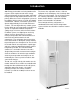
Introduction 2001 Energy SxS models are being introduced in response to the requirement for more energyefficient refrigerators by mid year 2001, along with having feature and operation enhancements. The primary differences in this refrigeration system are the adaptive defrost system (see Pub. # 31-9062), control board, software, and control systems that operate independently in fresh food and freezer sections.
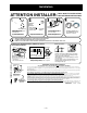
Installation ATTENTION INSTALLER: FOR A QUALITY INSTALLATION, FOLLOW THESE INSTRUCTIONS. RAISE 9 IS COLDEST 0 IS OFF 4 3 3 7 8 8 2 5 6 2 5 6 9 9 0 1 4 7 CARDBOARD PROTECTS DOOR EDGES À@, ÀÀÀÀÀ ,,,,, @@@@@ ,,,,, @@@@@ ÀÀÀÀÀ À@,À@,À@,À@,À@,À@, DO NOT OVERTIGHTEN STRAP 1 ROLLERS ROLLER ADJUSTMENT HEX-HEAD BOLTS (4) • REMOVE AND DISCARD SKIDBOARDS and bolts used to hold skidboards. • Use PADDED HAND TRUCK to protect refrigerator finish.
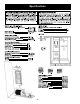
Specifications –4–
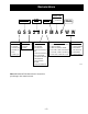
Nomenclature ENGINEERING NOMENCLATURE A = INIITIAL DESIGN CONFIGURATION VOLUME S = SIDE-BY-SIDE REF. 20 / 22 / 25 CU. FT. MODEL YEAR M = 2001 B = 1ST REVISION ETC.
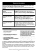
Warranty Information Sales slip or cancelled check is required as proof of original purchase date to obtain service under warranty. Note: Water filter cartridge warranty is 30 days. All warranty service is provided by our Factory Service Centers or an authorized Customer Care® technician. For The Period Of: GE Will Replace: One Year From the date of the original purchase Any part of the refrigerator which fails due to a defect in materials or workmanship.
Operating Characteristics Table of Contents Normal Operating Characteristics That Are Different from Previous Models . . 8 Abnormal Operating Characteristics (Incorrect Operation) . . . . . . . . . . . . . . . 8 Adaptive Defrost . . . . . . . . . . . . . . . . . . . . . . . . . . . . . . . . . . . . . . . . . . . . . . . . . . 8 Cooling Operation (Adaptive Defrost) . . . . . . . . . . . . . . . . . . . . . . . . . . . . . . . . 8 Pre-Chill Operation (Adaptive Defrost) . . . . . . . . . . . . . . . .
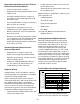
Normal Operating Characteristics That Are Different from Previous Models • Length of time the compressor has run since the last defrost cycle. • Icemaker auger rotates clockwise. • • Evaporator fan running, without compressor or condenser fan. Amount of time the defrost heaters were on in the last defrost cycle. • Adaptive Defrost is divided into 5 separate cycles. Those operations are: Post Dwell (Adaptive Defrost), compressor, and condenser fan on with evaporator fan off after defrost cycle.
into a continuous cool mode (pre-chill). During prechill, the freezer temperature may be driven below the set point. However, the fresh food temperature will be regulated by the damper. Pre-chill will last for 2 hours. These models do not have a defrost holdoff. Defrost Heater Operation (Adaptive Defrost) After 2 hours of pre-chill operation, the main control board turns off the compressor, condenser fan, and evaporator fan.
Hinge System and Door Closure Dispenser Lock When the dispenser system is locked, no dispenser command will be accepted. This includes the dispenser cradle and will prevent accidental dispensing that may be caused by children or pets. If a pad is pressed with the system locked, it will be acknowledged with 3 pulses of the LOCK LED accompanied by an audible tone.
Airflow (Cabinet Interior) “Jelly Roll” Condenser The freezer compartment is designed so that when the evaporator fan is operating, air is drawn into the bottom of the air tunnel and through the evaporator. The cold air is then pushed out into the top of the freezer. The fresh food compartment receives chilled air via an electronic damper positioned at the top, rear of the refrigerator between the freezer compartment and the fresh food compartment.
Main Control Board COMMUNICATION DAMPER COILS THERMISTOR ENCODER INPUTS MODEL SELECT INPUTS J3 J1 9 1 10 1 J4 1 5 1 COMM 2 +12V 3 -COM 4 DI 5 DO INPUT/OUTPUT J5 1 ACCUMULATED FF AND FRZ DOOR OPENINGS (MINUTES) 6 INPUTS FAN OUTPUTS J2 8 1 COMPRESSOR RUN TIME (MINUTES) DEFROST HEATER ON TIME (MINUTES) PROCESSING UNIT 1 OUTPUTS AND DEFROST OUTPUTS – 12 – DOOR SWITCH INPUTS K6 WATER K2 C/CR K1 AUGER AUGER WATER CRUSHER K7 PAN/HTR QC K5 J7 OCH DFF DFZ N PAN_HTR COMPRE
General Locator Views Temperature Controls Tech Data Sheet Location Freezer Light Switch Fresh Food Light Switch Damper Fresh Food Thermistor Evaporator Fan Evaporator Thermistor Evaporator Freezer Thermistor GEA00914 – 13 –
Main Control Board Condenser Fan Jelly Roll Condenser Compressor Water Solenoids Capacitor GEA00917 Overload and Relay (under cover) – 14 –
Mechanical Disassembly Table of Contents Door Gasket . . . . . . . . . . . . . . . . . . . . . . . . . . . . . . . . . . . . . . . . . . . . . . . . . . . . . . 17 Door Handles . . . . . . . . . . . . . . . . . . . . . . . . . . . . . . . . . . . . . . . . . . . . . . . . . . . . . 17 Doors and Door Hinges . . . . . . . . . . . . . . . . . . . . . . . . . . . . . . . . . . . . . . . . . . . . 17 Door Removal . . . . . . . . . . . . . . . . . . . . . . . . . . . . . . . . . . . . . . . . . . . . . . . . . .
Fresh Food Thermistor . . . . . . . . . . . . . . . . . . . . . . . . . . . . . . . . . . . . . . . . . . . . . 24 Door Dispenser Control Panel . . . . . . . . . . . . . . . . . . . . . . . . . . . . . . . . . . . . . . . 24 Door Dispenser Target Switch . . . . . . . . . . . . . . . . . . . . . . . . . . . . . . . . . . . . . . . 24 Ice Crusher . . . . . . . . . . . . . . . . . . . . . . . . . . . . . . . . . . . . . . . . . . . . . . . . . . . . . . 25 Ice Dispenser Drive Motor . . . . . . . . . . . . . .
Door Gasket The rear flange of the gasket is positioned between the inner and outer door panels. The screws under the gasket flap must be loosened. 1. Remove the door bins. 2. Loosen 40 screws located under the door gasket. 3. Remove the gasket from the interior of the door liner. Note: The back side of the door liner has doublesided tape at the corners. Doors and Door Hinges IMPORTANT: The freezer door is not adjustable.
Cam with Thimble Screw Cam Riser Hinge Adjustment Pin Hinge GEA00909 3. Remove the base grille. 4. Disconnect the water supply tube. To disconnect the tube, push in the white collar on the quick connector and pull the tube out. 9. Remove the screw, hinge cam, and thimble from the bottom of the door. 10. Fresh Food Door Only: Remove the hinge adjustment pin and cam riser from the lower hinge. 11. Freezer Door Only: Remove the cam riser and washer from the lower hinge. 12.
2. Disconnect the connectors for the door light switch and temperature control switches. Connectors Encoder Board Freezer Door Light Switch GEA00870 3. Disconnect the connectors for the light and temperature control encoders. The freezer door light switch is located on the left of the freezer compartment. 4. Disconnect the temperature control encoder connector. 1. Slide a small flat-blade screwdriver under the switch and push the locking tab. Pull out the switch. 5.
2. On models without a replacement LED, apply the year and month sticker to the new cartridge. The QuickSpace shelf splits in half and slides under itself to allow for storage of tall items on the shelf below. To adjust this shelf: 3. Line up the arrow on the cartridge with the cartridge holder. Place the new cartridge up and inside the holder. Do not push it into the holder. 1. Tilt the shelf up until the tab disengages from the shelf track. 2. Lift the lower tab out of the shelf track. 4.
Freezer Light The freezer light is attached to the evaporator fan housing. 1. Remove the light cover by lifting it off the tabs. 2. Replace the appliance light bulb. GEA00874 Icemaker The icemaker is located in the rear of the freezer compartment. The icemaker must be replaced as a complete unit. GEA00875 1. Slide out the upper icemaker dispenser tray and drawer. Door Shelf Extenders Detachable shelf extenders deepen and enclose fixed door shelves, providing more storage and greater storage flexibility.
Ice Dispenser Drive Mounting Screws The ice dispenser drive turns the ice dispenser auger in either crushed or cube mode. 1. Remove 2 Phillips screws from the ice dispenser drive. 2. Slide the dispenser out until the cable connector is visible. Splash Baffle 3. Disconnect the cable and remove the dispenser drive. GEA00879 3. Lift up the icemaker and slide it out until the cable connection is exposed. 2 Screws Note: When replacing the icemaker, the fill cup and splash baffle must be reused. 4.
4. Remove 4 Phillips screws from the evaporator cover. 5. Remove the evaporator cover. 6. Disconnect the evaporator fan cable connectors and the ground wire. 7. Loosen 2 Phillips screws from the evaporator fan mounting. Defrost Heater and Freezer Thermistor The defrost heater warms the evaporator during the defrost mode of operation. The freezer thermistor, located at the bottom left side of the freezer compartment, senses the temperature in the freezer. 1. Complete steps 4 and 5 in the previous procedure.
Door Dispenser Control Panel Overtemperature Thermostat and Evaporator Thermistor The main control board monitors the resistance of the evaporator thermistor. The main control board will terminate the defrost cycle when a predetermined temperature (60° F) is reached. The over-temperature thermostat is a redundant defrost terminating device. It will also terminate defrost in the event of a failure of the evaporator thermistor.
3. Turn over the ice bucket and ice dispenser cover. Remove the Phillips screw. 4. Remove the cover. 5. Remove the Phillips screw for the ice cube control linkage and slide the linkage to the rear of the ice bucket. 4. Spread out the locking tabs and remove the switch. 6. Using a pair of pliers, break the tabs off the back cover. 5. Push the chute duct door locking tabs back and raise the assembly above the locking tabs. 7.
6. Disconnect the wire connectors. 2. Remove 2 Phillips mounting screws. 3. Pull out the motor. 4. Disconnect the wire connectors. Solenoid 5. Remove the drive fork and nut. Solenoid Mounting Screws Motor Mounting Screws Ground Wire Motor GEA00695 7. Remove 2 solenoid mounting screws. 8. Slide the solenoid out of the housing. GEA00919 Evaporator 6. Disconnect the motor wiring connectors. Air is driven across the evaporator coils to produce cold air for the freezer and fresh food compartments.
4. Remove 2 screws from the condenser fan cover. Screws 5. Pull out the fan until the electrical connector is exposed. 6. Disconnect the electrical connector. GEA00894 5. With a file, score the capillary tube just above the soldered section. Break off the soldered section of the capillary tube. This helps prevent solder from plugging the tube during assembly. Electrical Connector 6. Place a new evaporator into the freezer and insert the suction line and capillary tube into the evaporator. 7.
IMPORTANT: To ensure proper door closure, the refrigerator rollers must be adjusted to level the refrigerator. This is different from previous models. Main Control Board The main control board is located in the back of the unit. This board controls the operation of the unit. 1. Unplug the unit and remove the cover. Adjusting Screw 2. Disconnect all wiring harness connectors from the main control board. 3. Remove the board by unlocking the four plastic board standoffs located on the board.
Cable Connector GEA00900 4. Remove 2 Phillips screws from the solenoid connection. 5. Disconnect the water tube and remove the solenoid. Fresh Food Air Damper The fresh food air damper is located in the upper left corner of the fresh food compartment. The damper opens to allow cold air to circulate from the freezer to the fresh food compartment. 1. Remove 2 damper cover screws. 2. Remove the damper cover. 3.
Notes – 30 –
Notes – 31 –
Diagnostics Table of Contents Efficient Use of Diagnostics . . . . . . . . . . . . . . . . . . . . . . . . . . . . . . . . . . . . . . . . . 32 Failure Causes (Table 1) . . . . . . . . . . . . . . . . . . . . . . . . . . . . . . . . . . . . . . . . . . . . 33 Main Control Board (Low-Voltage Side) . . . . . . . . . . . . . . . . . . . . . . . . . . . . . . . 34 Main Control Board (120 VAC Side). . . . . . . . . . . . . . . . . . . . . . . . . . . . . . . . . . .
Table 1.
Main Control Board (Low-Voltage Side) (Sample only, check schematic shipped with product) 1 - Tan 2 - 13VDC Red 3 - Blk-DC Common 4 - Violet 5 - Wht 1 - Not Used 2 - Yel / Blu Band 3 - Wht / Blu Band 4 - Brn 5 - 5VDC Blu / Wht 1 - Blu / Yel 2 - Wht / Brn 3 - Red / Blk 4 - Yel J4 J1 PERSONALITY PIN - NONE - 20 Cu. Ft. - Pin 8 - 22 Cu. Ft. - Pin 9 - 25 Cu. Ft.
Main Control Board (120 VAC Side) PROCESSING UNIT 1 OUTPUTS K6 WATER K2 C/CR AUGER COMMON CRUSHER K1 AUGER J7 OCH DFF DFZ WATER K7 PAN/HTR QC K5 K3 PAN_HTR N LINE DEFR DEFROST COMP L1 K4 COMP PRE-CHILL DEFROST 2 J6 COOLING COMPRESSOR AND DEFROST OUTPUTS DOOR SWITCH INPUTS J7 1 - Blk / Wht 2 - Violet / Blk 3 - Yel 4 - Gry 5 - Not Used 6 - Violet 7 - Red 8 - Blk 9 - Orn – 35 – GEA00905
Main Control Board Locator Table (Low-Voltage Side) Wire Color Component Termination Connector Pin J1 1 Not used Not used Not used J1 2 Yellow/Blue Band Fresh food thermistor #1 J1 pin 2 to pin 5 = 2.8 to 3.5 VDC J1 3 White/Blue Band Freezer thermistor J1 pin 3 to pin 5 = 2.8 to 3.5 VDC J1 4 Brown Evaporator thermistor J1 pin 4 to pin 5 = 2.8 to 3.
Main Control Board Locator Table (Low-Voltage Side) Wire Color Component Termination Connector Pin Pin-to-Pin Voltage Reading J3 1 Blue/Yellow Damper J3 pin 1 to J4 pin 3 = Traveling Voltage 6.0 VDC J3 2 White/Brown Damper J3 pin 2 to J4 pin 3 = Traveling Voltage 6.0 VDC J3 3 Red/Black Damper J3 pin 3 to J4 pin 3 = Traveling Voltage 6.0 VDC J3 4 Yellow Damper J3 pin 4 to J4 pin 3 = Traveling Voltage 6.
Main Control Board Locator Table (120-VAC Side) Pin Wire Color Component Termination Pin-to-Pin Voltage Reading J7 1 Black/White Auger motor J7 pin 1 to J7 pin 9 = 120 VAC* J7 2 Violet/Black Cube solenoid J7 pin 2 to J7 pin 9 = 120 VAC* J7 3 Yellow Water valve J7 pin 3 to J7 pin 9 = 120 VAC* J7 4 Gray Auger motor interlock J7 pin 4 to J7 pin 9 = 120 VAC (freezer door shut) J7 5 Not used Not used Not used J7 6 Violet Fresh food door light switch feedback J7 pin 6 to J7 pin 9
Fresh Food Warm - Freezer Warm Basic refrigerator checks: Door gasket seal OK? Door switch - light turning off with door closed? Dispenser duct door closing properly? Repair as necessary No Yes Is the condenser fan running? Go to Condenser Fan Not Running Flowchart page 45 No Yes Is the evaporator fan running? No Go to Evaporator Fan Not Running Flowchart page 44 No Go to Compressor Not Running Flowchart page 47 Yes Is the compressor running? Yes Is the airflow within the freezer normal? No
Freezer Warm - Fresh Food Normal Check control settings and temperatures Food at a setting of 5 and 5 with no door openings for 12 hours should be: Fresh food 34 F to 42 F Freezer -8 F to +6 F Control settings require adjustment Adjust settings and allow 24 hrs to stabilize Control settings OK Basic refrigerator checks: Door gasket seal OK? Door switch - light turning off with door closed? Dispenser duct door closing properly? No Repair as necessary Yes Is the evaporator fan running? No Go to Eva
Fresh Food Warm - Freezer Normal Check control settings and temperatures Food at a setting of 5 and 5 with no door openings for 12 hours should be: Fresh food 34 F to 42 F Freezer -8 F to +6 F Control settings require adjustment Adjust settings and allow 24 hrs to stabilize Control settings OK Basic refrigerator checks: Door gasket seal OK? Door switch - light turning off with door closed? No Repair as necessary Yes Is the evaporator fan running? Go to Evaporator Fan Not Running Flowchart page 44
Fresh Food Too Cold - Freezer Normal Check control settings and temperatures Food at a setting of 5 and 5 with no door openings for 12 hours should be: Fresh food 34 F to 42 F Freezer -8 F to +6 F Control settings require adjustment Adjust settings and allow 24 hours to stabilize Control settings OK Low ambient? Is the room temperature above 55 F? No Advise consumer of refrigerator installation requirements No Go to Damper Not Operating Flowchart page 46 Damper should be closed when FF temperatures
Refrigerator Dead, No Sound, No Cooling Are the interior lights on? Check house supply voltage. Do you have 120VAC? No No House wiring problem Yes Check for 120VAC at 6 pin connector at rear of unit. Do you have 120VAC? No Repair or replace power cord Yes Yes Repair wiring connections at 6 pin connector If dispenser model, does dispenser operate? (If non-dispenser, follow No statement path first) No Unplug J2 connector from main control board.
Evaporator Fan Not Running Always check fan for obstruction first. Unplug refrigerator to reset main control board. Warm freezer thermistor to 70 F and set temperature controls to 5 and 5. Reconnect power. At the evaporator fan connector, check for 13VDC from the red to white wire and 8-13VDC from the white to yellow wire. Is the voltage correct for both? Yes Replace evaporator fan motor No Unplug J2 connector on the main control board.
Condenser Fan Not Running Always check fan for obstruction first. Unplug refrigerator to reset main control board. Warm freezer thermistor to 70 F and set temperature controls to 5 and 5. Reconnect power. At the condenser fan connector, check for 13VDC from the red to white wire and 11-13VDC from the white to yellow wire. Is the voltage correct for both? Yes Replace condenser fan motor No Unplug J2 connector on the main control board.
Damper Door Not Operating Push on damper door to check manual movement. Is the damper door stuck? Yes Damper jammed Remove blockage or replace damper No Push damper halfway closed. Unplug refrigerator to reset main control board. Set temperature controls to 5 and 5 Reconnect power.
Compressor Not Running Unplug refrigerator Warm freezer thermistor to 70 F Connect power and set temperature controls to 5 and 5. Is the compressor running? Adjust settings and allow 24 hours to stabilize Yes No Check for 120VAC at connector J7-9 orange wire to TERMINAL-J8 black wire. Do you have 120VAC? Yes Direct test the compressor.
Heavy Frost on Evaporator First, always check door ajar, customer usage - numerous door openings, etc... Unplug refrigerator from power. Unplug blue connector from main board. Measure between blue wire on connector and neutral orange wire on main board J7, pin 9.
Table 2. Thermistor Values Temperature Degrees (C) Temperature Degrees (F) Resistance in KiloOhms -40 -40 166.8 kΩ -35 -31 120.5 kΩ -30 -22 88 kΩ -25 -13 65 kΩ -20 -4 48.4 kΩ -15 5 36.4 kΩ -10 14 27.6 kΩ -5 23 21 k Ω 0 32 16.3 kΩ 5 41 12.7 kΩ 10 50 10 kΩ 15 59 7.8 kΩ 20 68 6.2 kΩ 25 77 5 kΩ 30 86 4 kΩ 35 95 3.2 kΩ 40 104 2.6 kΩ 45 113 2.2 kΩ 50 122 1.8 kΩ 55 131 1.5 kΩ 60 140 1.
Component and Connector Locator Views Evaporator Fan Light Evaporator Thermistor Defrost Thermostat Evaporator Defrost Heater Freezer Thermistor GEA00916 – 50 –
Fresh Food Light Switch Damper Fresh Food Thermistor Fresh Food Lights GEA00913 – 51 –
Main Control Board Condenser Fan Jelly Roll Condenser Compressor Water Solenoids Capacitor GEA00917 Overload and Relay (under cover) – 52 –
Main Control Board (120 VAC Side) PROCESSING UNIT 1 OUTPUTS K6 WATER K2 C/CR AUGER COMMON CRUSHER K1 AUGER J7 OCH DFF DFZ WATER K7 PAN/HTR QC K5 K3 PAN_HTR N LINE DEFR DEFROST COMP L1 K4 COMP PRE-CHILL DEFROST 2 J6 COOLING COMPRESSOR AND DEFROST OUTPUTS DOOR SWITCH INPUTS J7 1 - Blk / Wht 2 - Violet / Blk 3 - Yel 4 - Gry 5 - Not Used 6 - Violet 7 - Red 8 - Blk 9 - Orn GEA00905 NOTE: Refer to the Main Control Board Locator Tables in the Diagnostics chapter for more informat
Schematics FREEZER DOOR DC DUCT SOLENOID EMI FILTER (WHEN APPLICABLE) R = 48Ω HTR 4 AC LINE VOLTAGE ORANGE VIOLET J4-4 WHITE WHITE WHITE J4-5 J1-5 J-9 J7-6 VIOLET ORANGE OVER TEMPERATURE THERMOSTAT (When Apllicable) VIOLET VIOLET J1-6 GRAY J1-3 J1-4 J1-5 RED/YELLOW J1-2 PINK/BLACK J1-1 YELLOW ON WHITE PINK VIOLET/BLACK WHITE J3-5 FF Control ENCODER BOARD WHITE – 54 – J7-7 J7-4 FREEZER DOOR INTERLOCK ORANGE ORANGE RED GRAY (AUGER INPUT) BROWN ORANGE FRESH FOOD LIGHT(S)
– 55 –
– 56 – Defrost Heater Pin 1 J9 Pin 9 J7 Pin 8 Pin 7 Pin 6 Pin 5 Pin 4 Pin 3 Pin 2 Pin 1 Neutral NIC FZ Door Switch FF Door Switch QuickChill Heater Auger Motor Interlock Water Valve Crusher Solenoid Auger Motor Pin 2 QuickChill Htr. Pin 1 QuickChill Htr.
Notes – 57 –
Illustrated Parts Catalog – 58 –
– 59 –
– 60 –
– 61 –
– 62 –
– 63 –
– 64 –
– 65 –
– 66 –
– 67 –
– 68 –