Turbo Air Inc. 1250 VICTORIA ST. CARSON, CA 90746, USA PRINTED DATE: May. 2003 S/M No.
S/M No. : Service Manual Microwave Oven Model: TMW-1100E TMW-1100EC TMW-1100M TMW-1100MC TMW-800T TMW-800TC http://www.turboairinc.com May.
PRECAUTIONS TO BE OBSERVED BEFORE AND DURING SERVICING TO AVOID POSSIBLE EXPOSURE TO EXCESSIVE MICROWAVE ENERGY (a) Do not operate or allow the oven to be operated with the door open.
TMW-800T / TMW-800TC SPECIFICATIONS .............................................................................................................................................................43 EXTERNAL VIEW..............................................................................................................................................................44 1. OUTER DIMENSION............................................................................................................................
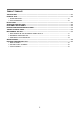
SAFETY AND PRECAUTIONS CAUTION : This Device is to be Serviced Only by Properly Qualified Service Personnel. Consult the Service Manual for Proper Service Procedures to Assure Continued Safety Operation and for Precautions to be Taken to Avoid Possible Exposure to Excessive Microwave Energy. 1. FOR SAFE OPERATION Damage that allows the microwave energy (that cooks or heats the food) to escape will result in poor cooking and may cause serious bodily injury to the operator.
SPECIFICATIONS MODEL TMW-1100E / TMW-1100EC POWER SUPPLY POWER CONSUMPTION 120V~60HZ, SINGLE PHASE WITH GROUND MICROWAVE 1500 W / 1600 W GRILL COMBINATION MICROWAVE ENERGY OUTPUT 1100 W MICROWAVE FREQUENCY 2450MHz OUTSIDE DIMENSIONS (W X H X D) 560X344X483mm (22.0X13.5X19 in.) CAVITY DIMENSIONS (W X H X D) 369X221X400mm (14.5X8.7X15.7 in.) NET WEIGHT APPROX. 16.5kg (36.4lbs) TIMER 59min. 99sec. FUNCTION SELECTIONS MICROWAVE POWER SELECTIONS 4 LEVELS CAVITY VOLUME 1.2 Cu.
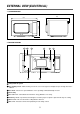
EXTERNAL VIEW (ELECTRICAL) 1. OUTER DIMENSION 483 344 560 2. FEATURE DIAGRAM 3 5 2 4 7 8 1 6 1 Safety interlock system 2 Door viewing screen - Allows viewing of food. The screen is designed so that light can pass through, but not the radiation. 3 Door hook - If the door is opened while the oven is operating, it will automatically shoot off. 4 Oven cavity 5 Door seal - Door seal maintains the microwave energy within the oven cavity. 6 Glass tray - Made of special heat resistant glass.
3. CONTROL PANEL 2 PROGRAM DEFROST 5 6 11 1 12 2 13 3 14 4 15 5 16 6 17 7 18 8 19 9 20 CHECK DOUBLE QUANTITY STOP/CLEAR 1 3 4 10 POWER 7 START/+30SEC 8 9 1 Display - Cooking time, power level, indicators are displayed. 2 Program - Used to save cooking data. 3 Defrost - Used to defrost foods. 4 Time Set Pad - Used to set the cooking time or cook preprogrammed foods. 5 Check - Used to check cooking data. 6 Double Quantity - Used to extend programmed cooking time.
EXTERNAL VIEW (MECHANICAL) 1-1. OUTER DIMENSION 483 344 560 2-1. FEATURE DIAGRAM 3 5 4 7 10 1 8 9 2 6 6. Glass cooking tray - Made of special heat resistant glass. Food in a proper receptacle is placed on this tray for cooking. 1. Safety interlock system 2. Door viewing screen - Allows viewing of food. The screen is designed so that light can pass through, but not the radiation. 7. Cover Stirrer - Protects the microwave outlet from splattering of foods being cooked. 3.
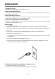
INSTALLATION 1. Steady, flat location. This microwave oven should be set on a steady, flat surface. 2. Leave space behind and side. All air vents should be kept clear. If all vents are covered during operation, the oven may be overheated and, eventually, cause oven failure. 3. Away from radio, and TV sets Poor television reception and radio interference may result if the oven is located close to a TV, radio, antenna, or feeder and so on. Position the oven as far from them as possible. 4.
OPERATIONS AND FUNCTIONS (ELECTRICAL) 1. Connect the main lead to an electrical outlet. 2. After placing the food in a suitable container, open the oven door and put it on the glass tray. The glass tray must always be in place during cooking. 3. Close the door securely. 4. The oven door can be opened at any time during operation by touching the door release button on the control panel. The oven will automatically shut off. To restart the oven, close the door and then touch START. 5.
OPERATIONS AND FUNCTIONS (MECHANICAL) 1. Connect the main lead to an electrical outlet. 2. After placing the food in a suitable container, open the oven door and put it on the glass tray. The glass tray must always be in place during cooking. 3. Close the door securely. 4. Choose cooking power level by setting V.P.C knob to the desired position. Refer to cookbook for recommended power levels. 5. Determine cooking time. Consult cookbook for recipe timing.
DISASSEMBLY AND ASSEMBLY Cautions to be observed when trouble shooting. Unlike many other appliances, the microwave oven is high-voltage, high-current equipment. It is completely safety during normal operation. However, carelessness in servicing the oven can result in an electric shock or possible danger from a short circuit. You are asked to observe the following precautions carefully. 1. Always remove the power plug from the outlet before servicing. 2.
1. To remove cabinet 1) Remove three screws on cabinet back. 2) Push the cabinet backward. 2. To remove door assembly 1) Remove two screws which secure the stopper hinge top. 2) Remove the door assembly from top plate of cavity. 3) Reverse the above for reassembly. NOTE : After replacing the door assembly, perform a check of correct alignment with the hinge and cavity front plate.
3. To remove door parts. A04 A13 A05 A06 A07 A08 A09 A10 A12 A11 Door Assembly : 3511718600 A01 A02 A03 REF NO. PART CODE A01 3511610610 DOOR DECORATOR PART NAME SUS T0.4 DESCRIPTION 1 A02 7001401011 SCREW PAN 4*10 MFZN 2 A03 3512206200 DOOR FRAME ABS 1 A04 3517008100 BARRIER SCREEN*O GLASS T3.2 1 A05 3516602100 DOOR PLATE SBHG-1A T0.7 1 A06 3517007600 BARRIER SCREEN*I PE T0.
4. Method to reduce the gap between the door seal and the oven front surface. (1) To reduce gap located on part ‘A’. • Loosen two screws on stopper hinge top, and then push A the door to contact the door seal to oven front surface. • Tighten two screws. (2) To reduce gap located on part ‘B’. • Loosen two screws on stopper hinge under, and then push the door to contact the door seal to oven front surface. • Tighten two screws.
5. To remove control panel parts. Control panel Assembly : PKCPSWAJ00 REF NO. PART CODE PART NAME DESCRIPTION Q’TY B01 3511610410 DECORATOR C-PANEL SUS T0.4 B02 351852400 TOUCH PAD KOR-1P5CBA B03 3516728510 CONTROL PANEL ABS AF-348, VT-0826 1 B04 PKMPMSAJ00 PCB AS KOR-1P5CBA 1 B05 7122401211 TAP SCREW T2S TRS 4X12 MFZN 4 REMARK 1 (1) Remove the screw which secure the control panel, push up two snap fits and draw forward the control panel assembly.
5-1. To remove control panel parts. B01 B02 B03 B04 B05 B06 B08 B09 B07 B10 B11 Control panel Assembly : 3516728700 REF NO. PART CODE PART NAME DESCRIPTION Q’TY B01 3511610410 DECORATOR C-PANEL SUS T0.4 1 B02 3511611400 DECORATOR FILM PC T0.5 1 B03 3513407400 VPC KNOB ABS SG-0760D COATING 1 B04 3513407500 TIMER KNOB ABS SG-0760D COATING 1 B05 3516728500 CONTROL PANEL ABS VT-0825 1 B06 3515101600 SPRING FLAT SUS 301 T0.
6. To remove high voltage capacitor. 1) Remove a screw which secures the grounding ring terminal of the H.V. diode and the capacitor holder. 2) Remove the H.V. diode from the capacitor holder. 3) Reverse the above steps for reassembly. ◆ High voltage circuit wiring 7. To remove magnetron. 1) Remove a screw which secures the magnetron. 2) Remove the magnetron. 3) Reverse the above steps for reassembly.
8. To remove wind guide assembly. 1) Remove two screws which secures the wind guide assembly and cover hole *0 and noise filter. 2) Draw forward the wind guide assembly. 3) Pull the noise filter from the wind guide assembly. 4) Pull the fan from the motor shaft. 5) Remove two screws which secure the motor shaded pole. 6) Remove the motor shaded pole. 7) Reverse the above steps for reasembly. Noise Filter:Only KOR-1P5CBB KOR-1P55BB 9. To remove H.V.transformer. 1) Remove four screws holding the H.V.
INTERLOCK MECHANISM AND ADJUSTMENT(ELECTRICAL) The door lock mechanism is a device which has been specially designed to completely eliminate microwave radiation when the door is opened during operation, and thus to perfectly prevent the danger resulting from the leakage of microwave. (1) Primary interlock switch When the door is closed, the hook locks the oven door. If the door is not closed properly, the oven will not operate. When the door is closed, the hook pushes the button of the microswitch.
TROUBLE SHOOTING GUIDE Following the procedure below to check if the oven is defective or not. 1) Check grounding before trouble shooting. 2) Be careful of the high voltage circuit. 3) Discharge the high voltage capacitor. 4) When checking the continuity of the switches, fuse or high voltage tranformer, disconnect one load wire from these parts and check continuity with the AC plug removed. To do otherwise may result in a false reading or damage to your meter.
CONDITION Outlet has proper voltage Fuse does not blow. CHECK RESULT CAUSE REMEDY No Continuity Defective magnetron Replace Check continuity of magnetron Check continuity of power supply cord No Continuity Open power supply cord Replace Normal Defective touch control circuit Replace Malfunction of secondary interlock switch Replace Display do not shown countdown NOTE 1 All these switches must be replaced at the same time, please refer to “Interlock Mechanism And Adjustment”.
(TROUBLE 3) No microwave oscillation even though fan motor rotates.
(TROUBLE 4) The following visual conditions indicate a probable defective touch control circuit or membrane switch assembly 1. Incomplete segments, 1) Segments missing. 2) Partical segments missing. 3) Digit flickering other than normal display slight flickering. 4) " :0" does not display when power is on. 2. A distinct change in the display is not on when they should be. 3. One or more digits in the display are not on when they should be. 4. Display indicates a number different from one touched. 5.
INTERLOCK MECHANISM AND ADJUSTMENT(MECHANICAL) The door lock mechanism is a device which has been specially designed to completely eliminate microwave radiation when the door is opened during operation, and thus to perfectly prevent the danger resulting from the leakage of microwave. (1) Primary interlock switch When the door is closed, the hook locks the oven door. If the door is not closed properly, the oven will not operate. When the door is closed, the hook pushes the button of the microswitch.
TROUBLE SHOOTING GUIDE Following the procedure below to check if the oven is defective or not. 1. Check grounding before trouble shooting. 2. Be careful of the high voltage circuit. 3. Discharge the high voltage capacitor. 4. When checking the continuity of the switches, fuse or high voltage transformer, disconnect one lead wire from these parts and check continuity with the AC plug removed. To do otherwise may result in a false reading or damage to your meter.
Does the fan motor work when you shut the door and turn the timer? YES Does the oven lamp light? Does the turntable turn? NO Replace or repair oven lamp, turntable motor. YES Normal reading should be approx. 0Ω If microwave do not oscillate, check continuity of filament of magnetron. NO Continuity Check continuity filament tap (3.3V) of high voltage. No Continuity Replace high Voltage transformer Continuity Poor continuity Check continuity filament tap (3.3V) of high voltage.
MEASUREMENT AND TEST 1. MEASUREMENT OF THE MICROWAVE POWER OUTPUT Microwave output power can be checked by indirectly mmeasuring the temperature rise of a certain amount of water exposed to the microwave as directed below. PROCEDURE 1. Microwave power output measurement is made with the microwave oven supplied at rated voltage and operated at its maximum microwave power setting with a load of 100 ± 5cc of potable water. 2.
2. MICROWAVE RADIATION TEST CAUTION 1. Make sure to check the microwave leakage before and after repair of adjustment. 2. Always start measuring of an unknown field to assure safety for operating personnel from microwave energy. 3. Do not place your hands into any suspected microwave radiation field unless the safe density level is known. 4. Care should be taken not to place the eyes in direct line with the source of microwave energy. 5.
3. COMPONENT TEST PROCEDURE • High voltage is present at the high voltage terminal of the high voltage transformer during any cooking cycle. • It is neither necessary nor advisable to attempt measurement of the high voltage. • Before touching any oven components or wiring, always unplug the oven from its power source and discharge the capacitor. 1. High voltage transformer 1) Remove connections from the transformer terminals and check continuity. 2) Normal readings should be as follows : Secondary winding .
WIRING DIAGRAM (TMW-1100EC) 30
WIRING DIAGRAM (TMW-1100E) 31
WIRING DIAGRAM (TMW-1100MC) 32
WIRING DIAGRAM (TMW-1100M) 33
PRINTED CIRCUIT BOARD 1. CIRCUIT CHECK PROCEDURE 1. Low voltage transformer check The low voltage transformer is located on the P.C.B. Measuring condition: Input voltage: 120V / Frequency: 60Hz Terminal Voltage LOAD NO LOAD 6-8 DC 12V AC 25.8V 9-10 AC 3.4V AC 4.0V NOTE 1. Refer to Ciruit Diagram (point 4). 2. Secondary side voltage of the low voltage transformer changes in proportion to fluctuation of power source voltage. 3.
MP1 MP2 Measure point 35
3. When there is no microwave oscillation 1) When touching START pad, oven lamp does not turn on. Fan motor do not rotate, but cook indicator in display comes on. ✻ Cause : RELAY 2 does not operate. → refer to Circuit Diagram (point 3) - Check method POINT A B RELAY 2 ON 5VDC GND RELAY 2 OFF GND 12VDC STATE 2) When touching START pad, oven lamp turns on. Fan motor rotates and cook indicator in display comes on. ✻ Cause : RELAY 1 does not operate.
2. P.C.B.
3. P.C.B. LOCATION NO. NO NAME SYMBOL SPECIFICATION PART CODE Q’TY 3515600100 1 1 BUZZER BZ1 BM-20K 2 CAPACITOR CERA C1~9 HIKF 50V 0.1MF Z AXIAL CCZF1H104Z 9 3 CAPACITOR ELEC EC2 50V RS CEXE1H100A 1 4 CAPACITOR ELEC EC6 50V RSS 100MF (8X11.
EXPLODED VIEW AND PARTS LIST (ELECTRICAL) 1. DOOR ASSEMBLY Refer to Disassembly and assembly 2. CONTROL PANEL ASSEMBLY Refer to Disassembly and assembly 3.
✔ Caution : In this Manual, some parts can be changed for improving, their performance without notice in the parts list. So, if you need the latest parts information, please refer to PPL(Parts Price List) in Service Information Center (http://svc.dwe.co.kr).
EXPLODED VIEW AND PARTS LIST (MECHANICAL) 1. DOOR ASSEMBLY Refer to Disassembly and assembly 2. CONTROL PANEL ASSEMBLY Refer to Disassembly and assembly 3.
✔ Caution : In this Manual, some parts can be changed for improving, their performance without notice in the parts list. So, if you need the latest parts information, please refer to PPL(Parts Price List) in Service Information Center (http://svc.dwe.co.kr).
SPECIFICATIONS MODEL TMW-800T / TMW-800TC POWER SUPPLY 120V~60Hz, SINGLE PHASE WITH EARTHING MICROWAVE POWER CONSUMPTION 1,200 W GRILL COMBINATION MICROWAVE ENERGY OUTPUT 800W MICROWAVE FREQUENCY 2450MHz OUTSIDE DIMENSIONS (W X H X D) 465 x 279 x 370 mm (18.3 x 11.0 x 14.5 in) CAVITY DIMENSIONS (W X H X D) 290 x 211 x 306 mm (11.4 x 8.3 x 12.0 in.) NET WEIGHT Approx. 12 kg (26.5 Ibs.) TIMER 10 min. Dual Speed FUNCTION SELECTIONS MICROWAVE POWER SELECTIONS 5 LEVELS CAVITY VOLUME 0.
EXTERNAL VIEW 1. OUTER DIMENSION 2. FEATURE DIAGRAM 3 5 11 1 9 10 6 2 4 8 7 6. Glass cooking tray - Made of special heat resistant glass. Food in a proper receptacle is placed on this tray for cooking. 1. Safety interlock system 2. Door viewing screen - Allows viewing of food. The screen is designed so that light can pass through, but not the microwave. 7. Roller guide - This must always be used for cooking together with the glass cooking tray. 3.
INSTALLATION 1. Steady, flat location. This microwave oven should be set on a steady, flat surface. 2. Leave space behind and side. All air vents should be kept a clearance. If all vents are covered during operation, the oven may be overheated and, eventually, cause oven failure. 3. Away from radio, and TV sets Poor television reception and radio interference may result if the oven is located close to a TV, radio, antenna, or feeder and so on. Position the oven as far from them as possible. 4.
OPERATIONS AND FUNCTIONS 1. Connect the main lead to an electrical outlet. 2. After placing the food in a suitable container, open the oven door and put it on the glass tray. The glass tray must always be in place during cooking. 3. Close the door securely. 4. Choose cooking power level by setting V.P.C knob to the desired position. Refer to cookbook for recommended power levels. 5. Determine cooking time. Consult cookbook for recipe timing. Oven light turns on and cooling fan starts to operate.
DISASSEMBLY AND ASSEMBLY Cautions to be observed when trouble shooting. Unlike many other appliances, the microwave oven is high-voltage, high-current equipment. It is completely safety during normal operation. However, carelessness in servicing the oven can result in an electric shock or possible danger from a short circuit. You are asked to observe the following precautions carefully. 1. Always remove the power plug from the outlet before servicing. 2.
1. To remove cabinet 1) Remove three screws on cabinet back. 2) Push the cabinet backward. 2. To remove door assembly 1) Remove two screws which secure the stopper hinge top. 2) Remove the door assembly from top plate of cavity. 3) Reverse the above for reassembly. NOTE : After replacing the door assembly, perform a check of correct alignment with the hinge and cavity front plate. 3. To remove door parts. REF NO.
(1) Remove the gasket door from door weld as. (2) Remove the barrier screen inner from weld as. (3) Remove the door frame from door weld as. (4) Remove the stopper hinge top from door weld as. (5) Remove the spring and the hook. (6) Remove the barrier screen outer from door frame. (7) Reverse the above steps for reassembly. 4. Method to reduce the gap between the door seal and the oven front surface.
5. To remove control panel parts. REF NO. PART CODE PART NAME DESCRIPTION Q’TY B01 3513405450 KNOB VPC ABS SG-0760D, SG-176 1 B02 3513405460 KNOB TIMER ABS SG-0760D, SG-175 1 B03 3511603930 DECORATOR C-PANEL STS T0.6 1 B04 3516003950 SPECIAL DOUBLE TAPE SI-161 T0.15 1 B05 3516726320 CONTROL PANEL ABS VT-0826, AF-348 1 B06 3515101600 SPRING FLAT SUS 301 T0.
6. To remove high voltage capacitor. 1) Remove a screw which secure the grounding ring terminal of the H.V. diode and the capacitor holder. 2) Remove the H.V. diode from the capacitor holder. 3) Reverse the above steps for reassembly.
7. To remove magnetron. 1) Remove a screw which secure the magnetron. 2) Remove the magnetron. 3) Reverse the above steps for reassembly. NOTE : Never install the magnetron without the metallic gasket plate which is packed with each magnetron to prevent microwave leakage. Whenever repair work is carried out on magnetron, check the microwave leakage. It shall not exceed 4mW/cm2 for a fully assembled oven with door normally closed.
8. To remove wind guide assembly. 1) Remove two screws which secure the wind guide assembly and cover hole *0 and noise filter. 2) Draw forward the wind guide assembly. 3) Pull the noise filter from the wind guide assembly. 4) Pull the fan from the motor shaft. 5) Remove two screws which secure the motor shaded pole. 6) Remove the motor shaded pole. 7) Reverse the above steps for reasembly. Noise Filter:Only KOR-63555B 9. To remove H.V.transformer. 1) Remove four screws holding the H.V.transformer.
INTERLOCK MECHANISM AND ADJUSTMENT The door lock mechanism is a device which has been specially designed to completely eliminate microwave radiation when the door is opened during operation, and thus to perfectly prevent the danger resulting from the leakage of microwave.
TROUBLE SHOOTING GUIDE Following the procedure below to check if the oven is defective or not. 1. Check grounding before trouble checking. 2. Be careful of the high voltage circuit. 3. Discharge the high voltage capacitor. 4. When checking the continuity of the switches, fuse or high voltage transformer, disconnect one lead wire from these parts and check continuity with the AC plug removed. To do otherwise may result in a false reading or damage to your meter.
Does the fan motor work when you shut the door and turn the timer? YES Does the oven lamp light? Does the turntable turn? NO Replace or repair oven lamp, turntable motor. YES Normal reading should be approx. 0Ω If microwave do not oscillate, check continuity of filament of magnetron. NO Continuity Check continuity filament tap (3.3V) of high voltage. No Continuity Replace high Voltage transformer Continuity Poor continuity Check continuity filament tap (3.3V) of high voltage.
MEASUREMENT AND TEST 1. MEASUREMENT OF THE MICROWAVE POWER OUTPUT Microwave output power can be checked by indirectly measuring the temperature rise of a certain amount of water exposed to the microwave as directed below. PROCEDURE 1. Microwave power output measurement is made with the microwave oven supplied at rated voltage and operated at its maximum microwave power setting with a load of 1000±5cc of potable water. 2.
2. MICROWAVE RADIATION TEST CAUTION : 1. Make sure to check the microwave leakage before and after repair of adjustment. 2. Always start measuring of an unknown field to assure safety for operating personnel from microwave energy. 3. Do not place your hands into any suspected microwave radiation field unless the safe density level is known. 4. Care should be taken not to place the eyes in direct line with the source of microwave energy. 5.
3. COMPONENT TEST PROCEDURE • High voltage is present at the high voltage terminal of the high voltage transformer during any cooking cycle. • It is neither necessary nor advisable to attempt measurement of the high voltage. • Before touching any oven components or wiring, always unplug the oven from its power source and discharge the capacitor. 1. High voltage transformer (1) Remove connections from the transformer terminals and check continuity.
WIRING DIAGRAM (TMW-800TC) 60
NOTE : RD : RED WH : WHITE BK : BLACK GN : GREEN BR : BROWN POWER SUPPLY : SINGLE PHASE ONLY FUSE 61 BK WH 1 M GY V.P.C. 2 3 CL : CAVITY LAMP FM : FAN(BLOWER) MOTOR GM : GEARED MOTOR TM : TIMER MOTOR V.P.C.
EXPLODED VIEW AND PARTS LIST 1. DOOR ASSEMBLY Refer to Disassembly and assembly. 2. CONTROL PANEL ASSEMBLY Refer to Disassembly and assembly. 3.
NO PART CODE A00 B00 F01 F02 F03 F04 F05 F06 F07 F08 F09 3511715310 3516726660 3510805000 3516004100 3516109500 3518906300 7121300611 7122401211 7122401211 7112401011 35113XANT5 35113XEWT5 3511409500 7122401211 3518903400 7121300611 7121403011 3963821610 3512517000 3511800300 3518002400 3516004000 7272400811 3513003200 3518301600 3518400900 3518401000 3518117450 3516003700 3510311710 7112401011 3512000900 7272400811 3515201101 4415A17352 4415A66600 4415A17352 3513702620 3513811750 3513601500 7121400611 3
ABOUT THIS MANUAL VISION CREATIVE, INC. 중구 남대문로 5 가 526 대우재단빌딩 16 층 담 당 이준철님 TEL MODEL TMW-1100E(EC,M,MC),800T(TC) 접 2003.06.27 일 수 정 제 판 규 격 MEMO 1차 6차 2차 7차 3차 8차 4차 9차 5차 10차 인쇄 2003.07.10-표지수정 2003.07.14-40,42p 수정 2003.07.23-39,40,41,42p 수정 2004.03.