GE Fanuc Automation Programmable Control Products VersaMax Serial to Ethernet Adapter User's Manual GFK-1852 July 2000
GFL-002 Warnings, Cautions, and Notes as Used in this Publication Warning Warning notices are used in this publication to emphasize that hazardous voltages, currents, temperatures, or other conditions that could cause personal injury exist in this equipment or may be associated with its use. In situations where inattention could cause either personal injury or damage to equipment, a Warning notice is used. Caution Caution notices are used where equipment might be damaged if care is not taken.
Preface Content of This Manual Chapter 1. Introduction and Quick Start: Overview of applications and firmware options and a quick start procedure. Chapter 2. Network Interfaces: Port and power specifications. Chapter 3. Network Protocols: IP address, packing algorithm, and port number. Chapter 4. Configuration: Using the configuration software to set paramteters. Chapter 5. Monitor Mode and Firmware Upgrade: Using Monitor mode and upgrading the VMSE firmware. Chapter 6.
Contents Chapter 1 Introduction and Quick Start ....................................................... 1-1 Introduction ........................................................................................................ 1-1 VMSE Firmware Options .................................................................................... 1-2 SRTP/SNP Firmware.................................................................................... 1-2 Pass Thru Firmware..............................................
Contents Serial Interface Configuration....................................................................... 4-7 SNP T1 – T4 Timers..................................................................................... 4-7 SNP ID to IP Address Mapping ( only for SRTP/SNP Mode#2) .................... 4-7 PassThru Firmware Configuration Setup....................................................... 4-8 Basic Parameters ..........................................................................................
Contents Firmware Distribution ......................................................................................... 5-4 Firmware Download Using a Network Host......................................................... 5-4 Windows NT Procedure............................................................................. 5-4 Windows NT Command Line Example Code Explanation...................... 5-5 VMSE Firmware File List:.....................................................................
Contents LEDs..................................................................................................... 7-2 Case ...................................................................................................... 7-2 Dimensions ........................................................................................... 7-2 Weight .................................................................................................. 7-2 Appendix A IP Addresses .......................................
Chapter 1 Introduction and Quick Start Introduction The VersaMax IC200SET001 Serial to Ethernet Adapter (VMSE) brings network connectivity to factory floors. It is designed to connect industrial devices with serial interfaces to an Ethernet network using the TCP protocol family (TCP for transparent stream- and UDP for datagram applications).
1 VMSE Firmware Options The IC200SET001 VMSE has multiple firmware choices. All of the choices are shipped on the CD that is shipped with the VMSE unit. Upgrades and new firmware choices will be placed on the GE Fanuc WEB site, as they become available. The VMSE ships with the default SRTP/SNP firmware loaded in flash memory. SRTP/SNP Firmware The SRTP/SNP firmware is used to connect GE Fanuc PLCs or other devices, which support the SNP protocol, to Ethernet.
1 Introduction and Quick Start Quick Start The easiest way to configure the IC200SET001 VMSE is over Ethernet. The following steps need to be done, in the order listed, to configure the VMSE. Preliminary Step Connect the VSME to the Ethernet network. Default IP Address The VMSE is shipped with a default IP address of 0.0.0.0, which automatically enables the DHCP within the VMSE.
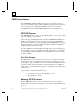
1 Figure 1-2. Results of the Ping Command B. Type arp -a (make sure you leave a space between arp and –a) at the MS-DOS prompt, then press the Enter key. You should see at least one entry in the ARP table, as shown in the next figure: ARP Table Figure 1-3. Results of the arp –a Command If the response is “No arp entries found,” repeat steps A. and B. to ping other devices until the arp -a command lists one or more devices.
1 Introduction and Quick Start do not complete this procedure and have to come back to it at a later time, you may have to start from the beginning. C. Type the following at the prompt, then press the Enter key: arp –s (IPAddress you want the VMSE to have) ( Mac Address of VMSE) This example uses: arp -s 3.16.27.44 00-20-4a-51-0e-5b NOTE: You will not see any reply on the screen (see Figure 1-5). D.
1 The following figure shows the screen before the Enter button is pressed: Figure 1-5. Screen Appearance Just Before Step G. G. After the Enter button is pressed in the previous step, the Telnet window opens with the VMSE Serial number, shown in the next figure. Confirm the Telnet connection by pressing the Enter key within 3 seconds.
1 Introduction and Quick Start Once you press the Enter key, the following VMSE Configuration screen will appear: Figure 1-7. The VMSE Configuration Screen H. Type s to save the IP address in the VMSE. (It is not necessary to press the Enter key.) The “Connection to host lost” Telnet dialog box will appear (this is normal) shown in the next figure: Figure 1-8. The “Connection to host lost” Telnet Box I.
1 J. Reconnect by typing telnet 191.12.3.77 9999 at the MS-DOS prompt, and then pressing the Enter key. This will take you to the VMSE Configuration screen, shown in Figure 1-7. K. Use this screen to configure the VMSE. An example is provided in the following “Configuration” section. Note The VMSE comes equipped with SNP/SRTP firmware by default.
1 Introduction and Quick Start Configuration This section is just an overview. See Chapter 4 for configuration details. Before proceeding with the configuration procedure, ensure that you have the correct firmware loaded in the VMSE. The VMSE comes equipped with SNP/SRTP by default. If you are using a different protocol, you must load the correct firmware for that protocol. See Chapter 5 for instructions. You have six Command choices at the Configuration screen Command Prompt (see next figure).
1 Configuration Example The following figure shows the results of pressing the 2 key to select the “CH1 Serial and Protocol Settings” parameter group. Notice that the first parameter in the group (“Protocol Mode”) is displayed. The current value is shown in parentheses (001 in this example) before the prompt. Simply pressing the Enter key would retain the current parameter value; typing 2 and pressing the Enter key would set the Protocol Mode parameter to Mode #2. Figure 1-10.
1 Introduction and Quick Start Once you finish configuring all of the parameters in the selected group (“CH1 Serial & Protocol Settings” in the above example), you will be returned to the Command Prompt where you can continue editing parameters or you can exit. Be sure to type S if you desire to save your changes when exiting. Modbus is a trademark of Gould, Inc. MS-DOS is a registered trademark of Microsoft, Inc.
Chapter 2 VMSE Interfaces Serial Interface The VMSE has RJ45 and screw block serial ports. The RJ45 port only supports RS232, whereas the screw block port supports RS232 and RS485/422. By setting the switch located on the face of the VMSE and configuring the VMSE setup, RS232 or RS485/422 can be selected. NOTE: The VMSE is a single serial port device, meaning that only one port can be used at a time. In the configuration menu, Channel One refers to either one of the ports being used. Figure 2-1.
2 Network Interface The VMSE supports 10 Mbit Ethernet through its RJ45 (10BaseT) connector. Hardware Address (MAC Address) The first three bytes are fixed, and read 00-20-4A. The fourth, fifth, and sixth bytes are unique for each VMSE and are used to generate the serial number. The address is in Hex notation. Power Requirements The VMSE is not shipped with a power supply. The required input voltage can vary between 9VDC and 30VDC with a maximum of 3 Watts.
Chapter 3 Network Protocols The VMSE product uses TCP/IP protocols for network communication. The supported standards are: ARP, UDP, TCP, ICMP, Telnet, TFTP, DHCP, and SNMP. For transparent connections, TCP/IP (binary stream) or Telnet protocols are used. Firmware upgrades can be made with the TFTP protocol. The IP protocol defines addressing, routing and data block handling over the network.
3 Port Number Every TCP connection and every UDP datagram are defined by a destination IP address and a port number. An IP address is necessary to address a device (host) on the network. A port number is necessary to address an application or a channel on a network host. The port number can be compared to an extension on a PBX (telephone) system. A Telnet application (login to a host with an ASCII terminal) is commonly assigned TCP port number 23.
Chapter 4 Configuration The VMSE can be configured using remote or local methods. Either use an ASCII terminal or a terminal emulation program to locally access the serial port, or use a Telnet connection to configure the unit over the network. The VMSE configuration is stored in nonvolatile memory and is retained without power. The configuration can be changed any time. The VMSE performs a reset after the configuration has been changed and stored.
4 NOTE: The easiest way to enter the configuration mode is to hold down the ‘x’ key at the terminal (emulation) and then power up the VMSE. This will ensure that the x characters will arrive in time. See Chapter 5 for more detail on using Serial communications to configure the VMSE. Entering Network Configuration Mode_ To configure over the network, a Telnet connection to port 9999 must be established. If you know the assigned IP address you can establish a Telnet connection to port 9999.
Configuration 4 Assigning a New IP Address If the IP Address of the VMSE is unknown or undefined, the following steps outline how to assign a temporary IP address over the network. 1. Set a static ARP with the desired IP address using the hardware address of the VMSE, which is printed on the product label. The following example shows the use of ARP in Win95/98/NT (from the DOS prompt) when the hardware address of the VMSE is 00-20-4A-01-64-0B.
4 Configuration Parameters After configuration mode is entered (confirm with ), the parameters can be changed; default values can be confirmed with the ENTER key. The parameters must be saved , and the VMSE performs a power reset. The Configuration for each of the firmware loads of the VMSE is slightly different. If you need to load a different firmware than is in the VMSE, load the firmware first, and then follow the directions for configuration for the appropriate firmware.
Configuration 4 SRTP/SNP Firmware – Configuration Setup Figure 4.1 shows the Main Configuration screen for SRTP/SNP Firmware. Figure 4-1. SRTP/SNP Firmware Configuration Screen When finished with this screen, you have three choices: • Press the “S” key to exit and save your changes. • Press the “Q” key to exit without saving your changes. • Press the “D” key to return to the default settings. Network/IP Settings To change the Network/IP settings, press ‘1’.
4 IP Address The IP address must be set to a unique value in your network. If you are not familiar with IP addresses, please refer to Appendix A. If the VMSE is given an address that is already in use it will not connect to the network. Gateway IP Address The router/gateway address is needed to communicate to other LAN segments. The default gateway must be set to the IP address of the router that connects these segments. This address must be within the local network.
4 Configuration Mode#2 – Mode#2 is used to connect a SNP master to the network using a VMSE. An example of this is: A Series 90 PLC with a serial port set up for SNP where COMMREQs are used to communication with other PLCs. Serial Interface Configuration Enter the interface setup as BBBB,D,P,S where BBBB is the baud rate ( default is 19200, D is the number of data bits (must be 8), P is parity (SNP defaults to O, the letter “O” not zero, S number of stop bits ( must be 1).
4 PassThru Firmware Configuration Setup Figure 4.2 shows the Main Configuration screen for PassThru Firmware. Figure 4-2. Pass Thru Firmware Configuration Screen When finished with this screen, you have three choices: • Press the “9” key to exit and save your changes. • Press the “8” key to exit without saving your changes. • Press the “7” key to activate the default settings. Basic Parameters To change the basic parameters (Server Configuration), press ‘0’.
4 Configuration IP Address The IP address must be set to a unique value in your network. If you are not familiar with IP addresses, please refer to Appendix A. If the VMSE is given an address that is already in use it will not connect to the network. Gateway IP Address The router/gateway address is needed to communicate to other LAN segments. The default gateway must be set to the IP address of the router that connects these segments. This address must be within the local network.
4 Interface Mode The line interface (I/F) mode is a bit-coded byte with the following meanings. It is entered in hexadecimal notation: )XQFWLRQ RS-232C RS-422/485 RS-485 2-wire 7 Bit 8 Bit No Parity Even Parity Odd Parity 1 Stop bit 2 Stop bit 0 0 1 1 1 0 1 0 0 1 0 1 1 0 1 0 1 1 1 1 Figure 4-3.
4 Configuration Port Number This setting is the source port number in TCP connections, and is the number used to identify the channel for remote initiating connections. The port number may not be set to 0 or 9999 (range: 1-65535). In general the port numbers 0..1023 are reserved in UNIX systems for specific applications. It is advisable to use numbers in the range 2000-30000 to avoid potential conflicts.
4 Connect Mode This parameter defines how the VMSE makes a connection and how it reacts to incoming connections over the network. Function Connection Acceptance -never accept incoming -accept incoming with active DTR only -accept unconditional (if not busy) Response on Serial to Connect -nothing (quiet) -character response: (C=conn., D=disc.
4 Configuration Example: The configured remote IP address within the VMSE is 129.1.2.3 and the TCP port number is 1234 : C121.2.4.5/1 complete override - connection is started with host 121.2.4.5, port 1. C5< ENTER > This means connect to 129.1.2.5, port 1234. C28.10/12< ENTER > This means connect to 129.1.28.10, port 12.
4 ATD0.0.0.0 If a remote IP address and port number are defined within the VMSE, this command will force the VMSE into “monitor mode”. ATDx.x.x.x Without a port number, this will make a connection to the given IP address (x.x.x.x) and the remote port number configured within the VMSE. All other 'AT' commands with “connect mode” set to 0x16 will acknowledge with an OK, but will not be acted upon.
4 Configuration Buffer Flushing With this parameter it is possible to control line handling and network buffers with connection startup and disconnect. Also, selection between two different packing algorithms is possible.
4 In some applications, CRC, Checksum, or other trailers follow the end-of-sequence character. In these cases, this option helps to adapt frame transmission to the frame boundary. If bit 4 is set, VMSE interprets the Sendchars as a 2-byte sequence; if reset, they will be interpreted independently. If bit 5 is not set, any other characters already in the serial buffer will be included in the transmission after a “transmit” condition is found.
Configuration 4 Modbus TCP/RTU Firmware Configuration Setup The next figure shows the Main Configuration screen for Modbus Firmware: Figure 4-7. Modbus Hardware Configuration Screen When finished with this screen, you have three choices: • Press the “S” key to exit and save your changes. • Press the “Q” key to exit without saving your changes. • Press the “D” key to return to the default settings. Network/IP Settings To change the Network/IP settings, press ‘1’.
4 Gateway IP Address The router/gateway address is needed to communicate to other LAN segments. The default gateway must be set to the IP address of the router that connects these segments. This address must be within the local network. Netmask A netmask defines how many bits from the IP address are to be taken as the network section and how many bits are to be taken as the host section (re class A: 8/24 (net/host), class B: 16/16, class C: 24/8 bits).
4 Configuration Advanced Modbus Protocol Settings To change the Channel settings, press ‘4’. The following values can be set/changed: Slave Addr/Unit ID , Modbus Serial Broadcasts, Character/Message Timeouts. Modbus ID to IP Address Mapping ( only used for Master) This setting is only available when Master is chosen. Entering “5” gives you the Mapping screen.
Chapter 5 Monitor Mode and Firmware Upgrade To enter monitor mode: The same principal as setting the parameters is used (see Section 4.3). Instead of entering three “x ” keys, key in “xx1”. Within one second of power-up, the VMSE will respond with a special prompt. To start the monitor mode without network functions (no network connections), enter “xx2”. To enter the monitor mode, in addition to “xx1” and “xx2”, you can also type “yyy” and log in.
5 Command Description GC x.x.x.x Get configuration as HEX records SC x.x.x.x Set configuration from HEX records PI x.x.x.x Check with Ping if x.x.x.x is alive and reachable AT Show the VMSE’s ARP table entries TT Shows all the incoming and outgoing TCP connections (used only with “monitor mode” from Telnet) NC Shows the IP configuration of the VMSE RS Resets the power on the VMSE SI x.x.x.x:n.n.n.n With this command, you can remotely assign an IP address to another VMSE, where x.x.x.
5 Monitor Mode and Firmware Upgrade received, the VMSE checks the integrity of the firmware image and then programs the new firmware in the flash ROM. Do not switch off the power supply at this time. A loss of power while reprogramming will result in a corrupt program image and a nonfunctional VMSE. To load firmware with Hyperterminal, enter monitor mode by resetting the VMSE and type xx1 after the * appears on the screen (you have about 1 second to type xx1).
5 Firmware Distribution To distribute the firmware of one VMSE to others, the “SF” command is used. After entering monitor mode on the VMSE, simply send the firmware with the “SF” command to the other devices. Firmware Download Using a Network Host Windows NT Procedure To download new firmware from a computer to a VMSE, it is necessary to have a TFTP (Trivial File Transfer Protocol) client send a binary file. Windows NT has a TFTP client built-in, but Windows 95/98 users must obtain TFTP software.
Monitor Mode and Firmware Upgrade 5 Windows NT Command Line Example Code Explanation C:\>tftp –i 3.16.27.40 PUT d:\snp42d.rom G1 1 2 3 4 5 7 6 1. C:\> is the command prompt 2. tftp is the execute command for the TFTP software 3. -i tells TFTP to send a binary file 4. The host field is the IP address of the target VMSE 5. PUT is the command that sends the file to the VMSE 6. The source file (including full path) to be sent to the VMSE 7.
5 Windows 95/98 Procedure Download the TFTP software as described below, then follow the instructions in the software’s built-in help file. Obtaining TFTP Software for Windows 95/98 As of this writing, a freeware TFTP software program called PumpKIN is available for Windows 95/98 from the following Web site: www.klever.net/kin/pumpkin.html Once the page appears, scroll down to the download selection table and download the “BANDWIDTH KILLER” version (either the .exe or .zip version).
Chapter 6 Serial Line Interfaces Serial Line Interfaces The VMSE has RJ45 and screw block serial ports. The RJ45 port only supports RS-232, whereas the screw block port supports RS-232 and RS-485/422. By setting the switch located on the face of the VMSE and by selecting the matching setting with the configuration software, RS-232 or RS-485/422 can be selected. NOTE: The VMSE is a one serial port device, meaning that only one port can be used at a time.
6 Screw Block Connector Pin-outs and Other Components The next figure and following table illustrate and describe the screw block connector pin-outs, LED operation, and other features of the VMSE. Pin 1 Figure 6-2.
Serial Line Interfaces Item Component Name Purpose 1 Screw terminal 2 Screw terminal 3 Screw terminal 4 Screw terminal 5, 6, 7 8 9 10 Screw terminal Screw terminal Reset switch LED (Red) RXD or RXA CTS or RXB RTS or TXB TXD or TXA NC GND RESET Fault or Configurati on Ready RS-232: RXD (Received Data) RS-422/485:RXA (Received Data -) RS-232: CTS (Clear to Send) RS-422/485: RXB (Received Data +) RS-232: RTS (Request to Send) RS-422/485: TXB (Transmit Data +) RS-232: TXD (Transmit Data) RS-422/
6 Cable Diagrams Cable IC200CBL504 RS-232 Serial Communications for VMSE RJ45 Serial Port to VersaMax Nano/Micro PLC RJ45 Port This cable is shipped in the box with the VMSE and can also be purchased separately. Nano/Micro PLC Connector (RJ45) VMSE Connector (RJ45) Pin 1 To PLC IC200CBL504 Marking denotes PLC end Pin 1 10cm (4 inches) Figure 6-4. IC200CBL504 Cable VMSE Connector PLC Connector 1 NC NC 1 2 NC RXD - 6 NC 2 4 - TXD TXD - 5 3 - RXD 8 – Sig. Gnd. Sig. Gnd.
6 Serial Line Interfaces User-Built Cable #1: VMSE RJ45 Serial to Miniconverter This cable is not currently sold by GE Fanuc. Details are provided so you can build your own cable. Application: To connect a VMSE’s RJ-45 Serial port (RS-232) to the RS-232 port of an IC690ACC901 Miniconverter (RS-232 to RS422/485). Female Connector (9-Pin, D-Sub) VMSE Connector (RJ45) To Miniconverter Pin 1 Figure 6-6.
6 User-Built Cable #2: VMSE RJ45 Serial to PC 9-Pin Sub-D For Serial Monitor/Load of VMSE This cable is not currently sold by GE Fanuc. Details are provides so you can build your own cable. Application: To connect a personal computer’s RS-232 serial port to a VMSE’s RJ-45 Serial port for the purpose of (1) monitoring VMSE operation or (2) downloading firmware to the VMSE. VMSE Connector (RJ45) Female Connector (9-Pin, D-Sub) To Personal Computer Serial Port Pin 1 Figure 6-8.
6 Serial Line Interfaces User-Built Cable #3: VMSE RJ45 Serial to PC 9-pin D-Sub This cable is not currently sold by GE Fanuc. Details are provides so you can build your own cable. Application: To connect the serial port (RS-232) of a personal computer (PC) running VersaPro software to a VMSE’s RJ-45 Serial port (RS-232). VMSE Connector (RJ45) Female Connector (9-Pin, D-Sub) To Personal Computer Serial Port in 1 Figure 6-10.
6 User-Built Cable #4: VMSE RS-422 Terminals to PLC This cable is not currently sold by GE Fanuc. Details are provides so you can build your own cable. Application: Connects the VMSE terminal block screw terminals to a PLC 15-pin, D-sub, RS422/RS-485 port such as is used on Series 90-30, Series 90-70, and VeraMax PLCs. Note that the VMSE switch must be set in the RS-422 position and the firmware configuration parameter “Interface Type” must be set to RS-422 (“Interface Type” set to RS-485 will not work).
Serial Line Interfaces 6 Using the VMSE on an RS-422/485 Multidrop Network The following figure shows an acceptable configuration for a multidrop network. This example shows only two slave devices; if additional slaves were added, termination would be required at the last slave device instead of at Slave #2.
6 Serial Port Connectors IBM-AT Style Personal Computer Serial Port Connector IBM-AT D-Sub, Male, 9-Pin Pin 1 Pin 6 External View Pin No. Signal Description 1 DCD Data Carrier Detect 2 RD Receive Data 3 TD Transmit Data 4 DTR Data Terminal Ready 5 GND Signal Ground 6 NC No Connection 7 RTS Request to Send 8 CTS Clear to Send 9 NC No Connection Figure 6-15.
6 Serial Line Interfaces 9-Pin, D-Sub PLC Serial Port Connector This connector is used for an RS-232 serial port on VersaMax CPUs. For additional information on VersaMax serial ports, please refer to the VersaMax PLC User’s Manual, GFK-1503.
6 15-Pin, D-Sub PLC Serial Port Connector This connector is used for an RS-485 serial port on all Series 90-30, Series 90-70, and VersaMax CPUs, and on some Nano/Micro PLCs. For information on Series 90 ports, refer to the Series 90 PLC Serial Communications Manual, GFK-0582. For VersaMax serial ports, refer to the VersaMax PLC User’s Manual, GFK-1503. For VersaMax Nano/Micro ports, refer to the VersaMax Micro PLCs and Nano PLCs User’s Manual, GFK-1645.
Serial Line Interfaces 6 RJ-11 PLC Serial Port Connector This connector is used for an RS-232 serial port on some Series 90-30 and Series 9070 CPUs. For additional information on these ports, please refer to the Series 90 PLC Serial Communications Manual, GFK-0582. RS-232, 6-Pin RJ-11 Pin 1 External View Pin Number 1 2 3 4 5 6 Signal Name CTS TXD 0V 0V RXD RTS Description Clear to Send Transmit Data Signal Ground Signal Ground Receive Data Request to Send Figure 6-18.
6 RJ-45 VersaMax Nano/Micro PLC Serial Port Connector Port 1 on the VersaMax Nano and Micro PLCs is an RS-232 port with an 8-pin RJ45 vertical jack. In addition to being a general serial communications port, this port is also used as the boot loader port for upgrading the PLC firmware on these PLCs. Note that the pin-out for this connector is different than that of the RJ-45 connector on the VMSE.
Serial Line Interfaces 6 IC690ACC901 Miniconverter 9-Pin, Male D-Sub Connector The RS-232 end of the IC690ACC901 Miniconverter has a 9-pin, male D-sub connector. Refer to the Series 90-30 PLC Hardware and Installation Manual, GFK0356, for a data sheet on the IC690ACC901 Miniconverter.
Chapter 7 Technical Data CPU, Memory, and Controllers • V.40 CPU, 10MHz clock • National Semiconductor DP839xx Ethernet Controller • 128 kByte RAM, 128 kByte Flash EPROM • 256 Byte E²PROM for parameter storage Serial Interface • RJ-45 connector for RS232 interface • Screw terminals for RS232 or RS422/485 interface • Speed software selectable 300 to 38.
7 LEDs • Four LEDs for Ethernet channel, link, activities, and error. • Two LEDs for serial channel status. Case • Plastic case for DIN rail mounting Dimensions Depth = 36mm (1.42”) 90mm (3.54”) 60mm (2.36”) Weight • 7-2 Approx. 150g (0.
Appendix A IP Addresses IP Addressing An IP address is a 32-bit value, divided into four octets of eight bits each. The standard representation is four decimal numbers (in the range of 0..255), divided by dots. Example: 192.2.1.123 This is called decimal-dot notation. The IP address is divided in two parts: network and host. To support different needs, three ”network classes” have been defined.
A Class C Network IP address 192.0.0.xxx to 223.255.255.xxx These network addresses are most common and are often used in small companies. These networks can consist of a maximum number of 254 hosts. Example: 192.7.1.9 (network 192.7.1, host 9) The remaining addresses 224.x.x.x - 239.x.x.x are defined as ”class D” and are used as a multicast addresses. The addresses 240.x.x.x. - 254.x.x.x are defined as "class E" and are reserved addresses.
A IP Addresses Netmask Examples Netmask 255.255.255.252 255.255.255.248 255.255.255.240 255.255.255.224 255.255.255.192 255.255.255.128 255.255.255.0 255.255.254.0 255.255.252.0 255.255.248.0 . . 255.128.0.0 255.0.0.0 Host bits 2 3 4 5 6 7 8 9 10 11 . . 23 24 Figure A-2. Netmask Examples Private IP Networks and the Internet If your network is not connected to the Internet and there are no plans to make such a connection you may use any IP address you wish.
A Network RFC’s For more information regarding IP addressing see the following documents.
Appendix B Binary to Hexadecimal Conversion Table Hexadecimal digits have values from 0..15, represented as 0...9, A (for 10), B (for 11) ... F (for 15). Use the following table to convert binary-to-decimal-to-hex: Decimal 0 1 2 3 4 5 6 7 8 9 10 11 12 13 14 15 Binary 0000 0001 0010 0011 0100 0101 0110 0111 1000 1001 1010 1011 1100 1101 1110 1111 Hexadecimal 0 1 2 3 4 5 6 7 8 9 A B C D E F Figure B-1.
Appendix C Declaration of Conformity Declaration of Conformity according to ISO/IEC Guide 22 and BS 7514 The following product: Product Name: VMSE Product Number(s): IC200SET001 Conforms to the following standards or other normative documents: Electromagnetic Emissions: C1SPR22: 1993 Class “A” EN55022, 1995 Class "A" Electromagnetic Immunity: EN50082-1, 1992 Product Safety: EN60950, 1988 +A1, A2, A3, A4 Supplementary Information: This product has been verified as being compliant within the cla
Index DTR disconnect, 4-14 A E ARP, 4-3 command example, 1-4 Automatic connection address, 4-12 B Baud rate configuration, 4-9 Broadcast address, A-2 Buffer flushing, 4-15 C Cable diagrams, 6-4 Class A network, A-1 Class B network, A-1 Class C network, A-2 Configuration memory, 4-1 parameters, 4-4 Telnet, 4-9 Ethernet, 2-2 External transceiver, 2-2 F Firmware download from VMSE to VMSE, 5-4 download via network host, 5-4 downloading via serial port, 5-2 VMSE options, 1-2 Flow control config.
Index LED port number, 4-11 remote TCP port, 4-11 send characters, 4-16 operation, 6-3 PassThru M MAC address, 2-2 Memory specifications, 7-1 Miniconverter 9-pin pin-out, 6-15 user-built cable, 6-5 Modbus ID to IP address mapping, 4-19 Modbus protocol advanced settings, 4-19 Modbus TCP/RTU configuration, 4-17 firmware, 1-2 Modem emulation mode, 4-13 Monitor VMSE cable, 6-6 Monitor mode results codes, 5-2 Monitor mode commands, 5-1 Multidrop, using VMSE, 6-9 config.
Index parameter setting, 4-16 Serial and Mode settings, 4-18 Serial interface, 4-18 operating range, 7-1 Timeout, inactivity, 4-15 specifications, 7-1 Serial line interfaces, 6-1 Serial port 15-pin pinout, 6-12 PC pin-out, 6-10 RJ-11 pin-out, 6-13 VersaMax 9-pin pinout, 6-11 U UDP, 3-1 datagram mode, 4-11 destination port no.