GE Oil & Gas 41005 Series Masoneilan* Cage Guided, Balanced Globe Valve Tech Spec Technical Specifications 09/2013
| GE Oil & Gas
Contents 1. General. . . . . . . . . . . . . . . . . . . . . . . . . . . . . . . . . . . . . . . . . . . . . . . . . . . . . . . . . . . . . . . . . . . . . . . . . . . . . 4 1.2 Serial Plate. . . . . . . . . . . . . . . . . . . . . . . . . . . . . . . . . . . . . . . . . . . . . . . . . . . . . . . . . . . . . . . . . . . . . . . . . . . . . . . . . . . . . . . . . . . . . . . . 4 1.3 After Sales Service . . . . . . . . . . . . . . . . . . . . . . . . . . . . . . . . . . . . . . . . . . . . . . . . . .
1. General Important This document contains all the instructions required for the installation, operation and maintenance of the equipment. Regular maintenance, strict observance of these instructions and the use of manufacturer’s replacement parts will guarantee optimum operation and reduce maintenance costs. 1.1 Scope The following instructions are designed to guide the user through the installation and maintenance of the 41005 series valves for all sizes and all pressure classes. 1.
2. Numbering System Actuator (2 Digits) Actuator Type and Action on Air Failure Conventional 37 – Open 38 – Close Cylinder 51– Double Acting 52 – Open 53 - Close Multispring 87 – Open 88 – Close Body S/A (5 Digits) Body Series 41 Cage guided globe Balanced Plug Seal Type Trim Type/Characteristic 0. Undefined 0. Undefined 3. Pressure energized PTFE seal ring 1. Standard cage/Linear 4. With pilot 2. Standard cage/Equal percentage 5. With seal ring 3. Lo-dB®/ anticavitation single stage/Linear 6.
conditions of your application, GE may have had to develop a special option which is the subject of an additional clause to this instruction manual. In this case, the instructions given in the additional clause always take precedence over the general instructions. 3.3 3. Installation 3.4 3.1 Cleanness of Piping Before installing the valve in the line, clean piping and valve of all foreign material such as welding chips, scale, oil, grease or dirt.
4. Disassembly 4.1 A. Remove the packing flange nuts (3) then remove the packing flange (4) and the packing follower (23). B. Removal of Actuator (Figures 15 and 16) Check that the exposed part of the valve plug stem (1) is clean enough for the bonnet (7) to be removed easily. Access to the internal components of the body should be accomplished with the actuator removed.
4.3 Disassembly of Valve Plug Stem 4.4 The valve plug stem is screwed and pinned into the valve plug (15). When the valve is of the 41405 type. To dismount the stem, the valve plug must be held as indicated below, taking care not to damage the guiding surfaces; the plug stem pin (9) is then removed. By means of flats or using a nut and counter-nut on the end of the stem, unscrew the stem taking care not to apply a bending moment which could deform it.
5. Maintenance – Repair 5.1 Packing Box Tightness of the packing box is obtained by compression of the packing (6). Compression must be achieved by evenly tightening the packing flange nuts (3) on the packing flange (4). Periodical retightening of the packing flange nuts is required to maintain tightness. Make sure that the packing is not over tightened as this could prevent smooth operation of the valve.
there is only slight damage, a light abrasive can be used. Otherwise the part must be replaced as soon as possible (see paragraph “Spare parts”). Guiding surface Guiding surface Pilot Seating surface • Spread a fine layer of high quality sealing compound on the seating surface. • Put the seat ring (13) in the body, noting the angle. • In case of 41375 valves, put the stack (48) on the seat ring and the cage (16) on the stack. Figure 5 5.2.
6. Valve Reassembly 6.1 6.1.2 Tightening of the plug stem Pinning the Valve Plug Stem The valve plug (15) and stem (1) assembly consists of a rod threaded into the valve plug and pinned in place. If the valve plug (15) [or the auxiliary pilot plug (20) in the case of a 41405 valve] needs to be replaced, it is recommended using a new stem.
6.1.4 Pinning 6.2.2 41405 and 41505 valves By means of a hammer, introduce the pin into the hole. Complete the pinning operation, taking care to ensure that the pin is recessed by the same amount at both sides. Using a ball tooling and hammer, caulk the pin hole edge of the plug. Place the assembly in the soft jaw chuck of a lathe to check alignment of the two parts; correct any alignment defects. 6.
Note: The cuts on each ring are to be placed at about 180° from each other. 6.2.5 41375 high temperature valve (232°C to 316°C) Caution: for the double-cage assembly, carry out the following operations: • Put the inner cage (16) upside down, (Figure 19) These valves are equipped with a seal ring composed of a jacket and a metallic spring and two backup rings (11G). • Encase the outer cage (75) on the inner cage, maintain them together with the two pins (76).
6.6 Tightening of Body Stud Nuts Alignment of internal parts In order to achieve perfect alignment of the seat ring and the valve plug, a force must be applied to the plug stem during tightening of the bonnet which results in correct relative positioning of the two parts. The force can be applied with the pneumatic actuator as follows: Place the actuator on the valve bonnet (7) by means of the yoke nut (33) or attachment screws and connect the valve plug stem to the actuator stem.
6.7 Assembly of Packing Box To assemble the packing box, proceed as indicated in the “maintenance” chapter, paragraph 5.1.1 or 5.1.2. Figure 11.
7. Actuator Caution: for coupling operations of actuators on valves, it is necessary as a preliminary: • to position the plug (15) on its seat ring (13). (In no case, one should not turn the plug on its seat, to avoid any deterioration of tightness seat). D. Supply air to the actuator at the initial pressure of spring range. E. Use the pointer (7) to set the travel scale (9) to the open valve position. F.
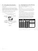
Actuator No Travel “X” Actuator 87 “X” Actuator 88 mm mm inches mm inches 10 20 0.8 130 5.12 10 38 1.5 138.2 5.44 16 20 0.8 203.2 8.00 16 38 1.5 228.6 8.50 16 51 2.0 235.7 9.28 16 63.5 2.5 241.3 9.50 23 20 0.8 209.5 8.25 23 38 1.5 218.9 8.62 23 51 2.0 231.6 9.12 23 63.5 2.5 243.6 9.59 inches 117.3 4.62 178.3 7.02 Figure 12. Position of top stem connector 7.4 Coupling of Actuator Type 88 No. 10, 16 and 23 (Figure 15) A.
7.5 Coupling of Air-to-Extend Actuator (Type 37) 7.6 (Figure 16) A. Push down on the plug stem (1) until the plug rests is seated. B. Attach the actuator to the valve bonnet with the yoke nut (33) or attachment screws. Apply a sufficient pressure to the diaphragm to extend the actuator stem by the normal valve travel for valves 41305, 41505, 41605 and 41905 and the travel minus the value of A in Figure 14 for 41405 valves. C. Assemble the two parts of the stem connector (51) and the point (58).
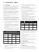
10 5 3 31 31 10 32 7 4 2 9 5 32 9 4 8 8 7 6 1 3 2 6 1 33 33 Model 88 No. 10-16-23 Model 87 No. 10-16-23 Parts Reference Ref. Designation 1 Hex nut 2 Bottom stem connector 3 Pointer screw 3 7 31 9 10 8 1 2 H 4 Top stem connector H 5 Cap screw, soc, head H 6 Connector Insert 7 Pointer 8 Screw, Pan head (travel scale) 33 9 Travel scale 10 Actuator stem 31 Yoke H Detail of 87/88 Model No. 6 32 Lock nut 33 Drive nut H Not provided for size 6 actuator Figure 15.
Parts Reference 72 36 Ref. 1 1/4” NPT 1/4” NPT 26 36 26 56 56 Plug stem coupling part the size (see detail) 33 33 Type 37 Air-to-extend actuator Type 38 Air-to-retract actuator 26 53 26 51 58 52 1 51 58 52 57 57 1 1 Coupling parts (No 18 and 18L actuators) Coupling parts (No 24 actuator) Detail of coupling types of plug stem Figure 16.
Body Sub Assembly 20 19 19 12 20 16 16 15 12 13 14 13 15 14 41405TRIM: TRIM : 2” 2" to 41405 to4"4” 41405 TRIM : 6"6” toto 18"18” 41405 TRIM: Diffuser Option diffuser option Figure 17. Internal parts of pilot plug valve – 41405 type 31 16 15 37 14 13 Figure 18.
| GE Oil & Gas
1 2 3 Packing with lateral connection 4 5 23 6 2" to 4" ≤ 1500 lb 10 10 2" to 6" 2500 lb 22 24 7 8 21 10 Without spring washer 6" to 16" ≤ 1500 lb 18", 20" and 24" and 8" to 16" 2500 lb 10 24 9 24 10 16 15 13 14 25 24 With spring washer 6" to 18" ≤ 1500 lb 20" and 24" and 8" to 16" 2500 lb 18 16 75 Double cage 17 11A 11B 11C 41095 76 ac 17 11D 41605 11E 11B High temperature 28 29 11G Valve working in Flow to close Flow to open 11F 11F 41405 & 41505 41305 41305 41375 Parts
DIRECT SALES OFFICE LOCATIONS AUSTRALIA Brisbane Phone: +61-7-3001-4319 Fax: +61-7-3001-4399 +39-081-7892-111 +39-081-7892-208 SOUTH AFRICA Phone: +27-11-452-1550 Fax: +27-11-452-6542 +61-8-6595-7018 +61-8-6595-7299 JAPAN Chiba Phone: Fax: +81-43-297-9222 +81-43-299-1115 SOUTH & CENTRAL AMERICA AND THE CARIBBEAN Phone: +55-12-2134-1201 Fax: +55-12-2134-1238 Melbourne Phone: +61-3-8807-6002 Fax: +61-3-8807-6577 KOREA Phone: Fax: +82-2-2274-0748 +82-2-2274-0794 SPAIN Phone: Fax: BELGIUM Phone: Fax: