
Technical Specifications

41005 Series Cage Guided, Balanced Globe Valve Tech Spec (September/2013) | 17
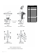
Actuator
No
Travel
“X”
Actuator 87
“X”
Actuator 88
mm inches mm inches mm inches
10 20 0.8 130 5.12
117.3 4.62
10 38 1.5 138.2 5.44
16 20 0.8 203.2 8.00
178.3 7.02
16 38 1.5 228.6 8.50
16 51 2.0 235.7 9.28
16 63.5 2.5 241.3 9.50
23 20 0.8 209.5 8.25
23 38 1.5 218.9 8.62
23 51 2.0 231.6 9.12
23 63.5 2.5 243.6 9.59
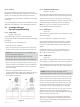
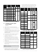
Figure 12. Position of top stem connector
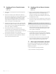
7.4 Coupling of Actuator Type 88
No. 10, 16 and 23
(Figure 15)
A. Tightly screw hex nut (1) onto the plug stem.
B. Tightly screw the top stem connector assembly onto
the actuator stem.
C. Push down the actuator and, at the same time, screw
on the yoke nut (33), then the bottom stem connector
assembly by screwing until they come into contact
with the hex nut (1).
D. Push down the actuator and tighten the yoke nut.
E. Unscrew the top stem connector to respect
dimension “X” in Figure 12.
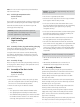
F. With the plug correctly positioned on the seat,
unscrew the bottom stem connector assembly to
bring it into contact with the top stem connector.
G. Supply air to the actuator until the stem has travelled
at least 15 mm.
H. Unscrew the bottom stem connector the number of
turns N1 specified in Figure 13 then lock manually
with hex nut (1).
Caution: for 41405 valves, use the N2 valve so ensure
tightness of the pilot plug.
I. Release the pressure in actuator so that the two
parts of connector come into contact and tighten the
socket head cap screws and nuts (1) and (32).
J. Shut off the supply pressure in the actuator and use
the pointer (7) to set the travel scale (9) to the closed
valve position and check that operation is correct.
Valve
size
(in)
ASME
class
Plug stem
diameters
mm (in)
N1
(turn)
N2
41405
(turn)
a
mm
(in)
2
150, 300 or
600
12.7
(1/2”)
1.5
3.5
1.9
(0.075)3 2500
2 900 to 2500 3.25
3 and 4 150 to 1500
15.87
(5/8”)
1.5 3.5
2.0
0.08)
4 and 6 2500
6 150 to 1500
19.05
(3/4”)
1.25 4.25
2.0
(0.08)
8 2500
8 150 to 1500
25.4
(1”)
1.25
4.5
2.3
(0.09)
10 2500
10, 12
and 16
150 to 1500
5
12 and 16 2500
18 150 to 1500
20 150 to 900
—
24 150 to 600
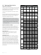
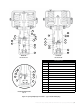
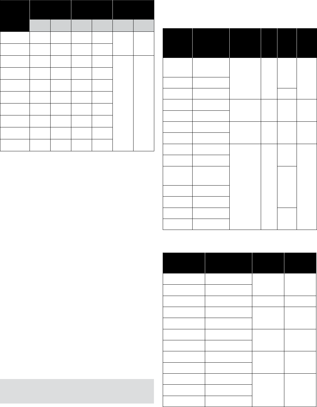
Figure 13. Reverse actuators – seating values for
41305 – 41505 – 41605 – 41905 valves
Valve size
(in)
ASME
class
Value A
mm (in)
Value a1
mm (in)
2 150, 300 or 600
2.5 (0.1) 4.4 (0.17)
3 2500
2 900 or 2500 2 (0.08) 3.9 (0.15)
3 and 4 150 to 1500
3 (0.12) 5 (0.2)
4 and 6 2500
6 150 to 1500
5 (0.2) 7 (0.27)
8 2500
8 150 to 1500
6 (0.24) 8.3 (0.33)
10 2500
10, 12 and 16 150 to 1500
7 (0.275) 9.3 (0.37)12 and 16 2500
18 150 to 1500
A = Pilot plug travel
Figure 14. Seating value for 41405 valves