0 ge.com Safetg Information Installation ............. Instructions Step-bLI-step instructions Operating Instructions Breaking a salt bridge Cleaning ® the nozzle .... 3-14 ........ ............. Water Models GXSH39E, GNSH45E 15, 18-20 sgstem Care and Cleaning Troubleshooting 16 16 17 ..................... softener 6-14 and venturi assemblg .................. Features .......................... Service Water Softening Sgstem 2 ......... ............. 15-20 21 Tips ......
IMPORTANT SAFETY INFORMATION. READ ALL INSTRUCTIONS BEFORE USING. WARNING! For Four safet_l, the information in this manual must be followed to minimize the risk of electric shock, property damage or personal injury. SAFETY PRECAUTIONS Check and comply with your state and local codes. You must follow these guidelines. iiiilDiiii:, Use care when handling the water softening system. Do not turn upside down, drop, drag or set on sharp protrusions.
I stall ti I str cti WAR N IN G: Read injury or property Water Softening System Models entire manual. Failure to follow G×SH39E and GNSH45E all guides and rules could cause personal damage. • Check with your state and/or local public works department guides as you install the Water Softening system. for plumbing codes.
Installation Instructions UNPACKING AND INSPECTION WHERE TO INSTALL THE SOFTENER Be sure to check the entire softener for ang shipping damage or parts loss. Also note damage to the shipping cartons. Contact the transportation compang for all damage and loss claims. The manufacturer is not responsible for damages in transit. Place the softener us close as possible to a sewer drain, or other acceptable drain point or standpipe.
Installation PLAN HOW YOU WILL INSTALL THE SOFTENER You must first decide how to run in and out pipes to the softener. Look at the house main water pipe at the point where you will connect the softener. Is the pipe soldered copper, glued plastic or threaded galvanized? What is the pipe size? TYPICAL INSTALLATION ILLUSTRATION Instructions WARNING: Use only lead-free solder and flux to prevent lead poisoning. See Typical Installation Illustration.
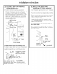
Installation Instructions BEFORE YOU BEGIN 1-_ INSTALL DRAIN FITTING • Turn off the gas or electric supplg to the water heater, in the possibilitg that the water heater mag be drained while draining pipes. • Push the drain fitting (lubricate o-ring seals with silicone grease) into the part of the valve as shown. • Turn off the water supplg to pipes to be cut and drain the house water pipes. • Snap the large plastic clip in place, from the top down as shown. Be sure the clip sneps into piece.
Installation PLUMB "IN" AND "OUT" PIPES TO AND FROM SOFTENER -4,CAUTION: Observe a,ofthefollowing cautions as you connect inlet and outlet plumbing, See Typical Installation lllustration. • BE SURE INCOMING HARD WATER SUPPLY IS DIRECTED TO THE SOFTENER VALVE INLET PORT. If house water flow is from the left, use a plumbing crossover as shown in Typical Installation Illustration. If house water flows up from the floor level, turn the bgpass valve upside down as shown.
Installation CONNECT AND RUN THE VALVE DRAIN HOSE {CONT.) • Elevating the drain hose may cause back pressure that could reduce the brine draw during recharge. If raising the drain line overhead is required to get to the drain point, measure the inlet water pressure to the softener first. For inlet pressures between 20 and 50 psi, do not raise higher than 8' above the floor. For inlet pressure above 50 psi, the drain line Hag be raised to a maximum height of 14'.
Installation I-_ INSTALL GROUNDING CLAMP A DANGER: Failure to properly attach ground clamp could result in electrical shock. If plumbing is metal, to maintain electrical ground continuity in the house cold water piping, install the included ground clamp as shown. • Clean pipe with emery paper in the area where the clamp is to be installed. • Install grounding clamps as shown, making sure clamps fit freely around pipe. • Make sure lock washer is in place. • Handtighten screwdriver.
Installation Instructions CONNECT TO ELECTRICAL POWER To gain access to the transformer/power cord assemblg, remove the salt hole cover from the softener. Unclip the tabs on the rear of the top cover and rotate the cover upward to remove. DO NOT PULL OR DISCONNECT WIRING. • The softener works on 24 volt-60Hz electric power. The included transformer changes standard 120-volt AC house power to 24 volts. Plug the transformer into a 120-volt outlet onlg.
Installation Instructions SET WATER HARDNESS NUMBER (CONT.} SET SALT LEVEL 3. When the display shows your water hardness (in grains per gallon), press MODE to accept. i. Press the MODE button You can get the grains per gallon (gpg} hardness of your water supply from a water analysis laboratory. If you are on a municipal supply, call your local water department. Or call Legend Technical Services, an independent laboratory, to request a water hardness test kit at 1.800.949.8220, Option 4.
Installation Instructions OPTIONAL CONTROL SETTINGS FEATURE: OTHER DATA DISPLAYS The controller features. display has several options and These models have an option to have the run display indicate different information. The information displayed on the top half of the display can be changed to one of the following: LOW SALT ALARM [,L_ ] The LOW SALT ALARM, when I.--J-I enabled, will sound the beeper LiE 4_/ un when the DAYS TO EMPTY value is 15 days or less.
Installation Instructions SIGNALS LOST TIME SIGNAL If time is lost on the display due to power interruption, the blue indicator light will flash 4 times every second, until the present time of day is entered. LOW SALT SIGNAL When the DAYS TO EMPTY drops to 15, the blue indicator light and DAYS TO EMPTY in the display will flash every second and the alarm will beep every 30 seconds (from 8:00 AM to 8:00 PM), to notify the user that the unit is running low on salt.
Installation SANITIZING Instructions PROCEDURES To complete the installation, sanitizing procedures. do the following water softener, and out the drain. This process takes approximately 2 hours. Care is taken at the factory to keep your water softener clean and sanitary. Materials used to make the softener will not infect or contaminate your water supply and will not cause bacteria to form or grow. However, during shipping, storage, installation and operation, bacteria could get into the softener.
About the water softener system, ge.com Service When the water softening system is providing soft water, it is called "Service." During service, hard water flows from the house main water pipe into the water softening system. Inside the water softening system resin tank is a bed made up of thousands of tiny, plastic resin beads. As hard water passes through the bed, each bead attracts and holds the hard minerals. This is called ion-exchanging. It is much like a magnet attracting and holding metals.
About the water softener Breaking system. a Salt Bridge Push tool into salt bridge to break Sometimes, a hard crust or salt bridge forms in the salt storage area. It is usuallg caused bg high humiditg or the wrong kind of salt. When the salt bridges, an emptg space forms between the water and salt. Then salt will not dissolve in the water to make brine. If the brine tank is full of salt, it is hard to tell if gou have a salt bridge. Salt is loose on top, but the bridge is under it.
ge.com Normal Operation, Control Displays During normal operation, the present time of dQy Qnd AM or PH and DAYSTO EMPTY show in the control displQy QreQ.When the demand computer determines a rechQrge is needed, RECHARGETONIGHT begins to flQsh in the display along with the present time. RECHARGE TONIGHT flashes until the next rechQrge start time, then chQnges to RECHARGE,which flQshes until the rechQrge is over.
About the water softener Service: sgstem. Electronic Demand ERRORCODE DISPLAYED Time Features ERR 01 POSSIBLEDEFECT • Motor inoperative • Wiring harness or connection to switch ERR 02 and Service ERR0,3 ERR04 • Position switch .Motor inoperative or wiring harness • Position switch or wiring harness • Control ,Control • Control ERR05 • Control • Position switch • Control To remove an error code: 1. Unplug transformer. 2. Correct defect. 3. Plug transformer in. 4.
ge.com Service: Manually Initiated Electronics 1. To enter diagnostics, press and hold the MODE button for 3 seconds until the Low Salt Alarm screen shows. to advance through Low Salt Alarm and Salt Efficiency options. See 2.PresstheMODEbutton2times Programming the Contro! for details on these two options. Diagnostics LEVEL SALT 2_ 4_/) 0 rl U ftmn Ft _ U UU l 1 3.
About the water softener Service: Manuallg sgstem. Advance Recharge Check NOTE:The control display must show a steady time (not flashing). 1. Press the RECHARGE@ button and hold in for three seconds. RECHARGEbegins to flash as the water softening system enters the fill cycle of recharge. Remove the brinewell cover and, using a flashlight, observe fill water entering the brine tank. If water does not enter the tank, look for an obstructed nozzle, venturi, fill flow plug or brine tubing.
Care and cleaning of the water softening system, Checking the Suit Storage Level and Refilling Brine (salt dissolved in water)is needed for each and every recharge. The water for making brine is metered into the salt storage area by the water softening system valve and control. However, you must keep the tank supplied with salt. When to refill with salt: If the blue indicator light and DAYSTO EHPTY are flashing, there is less than 15 days supply of salt. Refill with salt.
Before you call for service... Save time and money! Review the chart on this page first and you may not need to call for service. Troubleshooting Tips NO SOFTWATER - Most Common Problems: Check the following before calling for service: • Not enough salt-should be at least 1/3 full. Bypass valve in "Bypass" position-knob should be in the "OUT"(service)position. Hardness setting too low. Check hardness setting and adjust.
ge.com Problem Possible Water hard sometimes Using hot water while the water softening system is regenerating Avoid using hot water during water softening system recharge because the water heater will refill with hard water. SeeAutomatic Hard Water Bypass During Recharge section, page 15. Control HARDNESS number setting too low Pressthe MODE button until arrow points to HARDNESS.
Before you call for service... _ Troubleshooting Tips Problem Possible Causes What To Do Salty tasting or brown/yellow colored water after installation Unit not sanitized • Complete the Sanitization Procedureson page 14. • At completion of recharge cgcle (approx. 2 hrs),run water from faucets to purge the salty water. Low water pressure Check pressure. • Drainheight 8' or less,pressure should be minimum of 20 psi. • Drainheight above 8', pressureshould be minimum of 50 psi.
Notes.
Notes.
Parts list. ge.com 11 \ 4 28 16 19 /_ \ 146 13 12 _ 20 56 <__ 55 _,/ 21 55 22 56 10 29 / 24 9 26 27 25 33 J 32 27
Parts list. 141 j151 110 _------137 136 105 135 32 106 -- 130 146 I 1 145 124-11 115 123 122 \ .
Parts catalog, ge.com GENERAL ELECTRIC PARTS CATALOG G G X N S S H H 3 4 9 5 E E REF. NO. GE PART NO.
Parts catalog. GENERAL ELECTRIC PARTS CATALOG G 30 G × N S S H H 3 4 9 5 E E REF. NO. GE PART NO.
GE Water Softening System Warranty. (For Customers in the United States) All warranty service provided by our SmartWater T"Authorized Servicer Network. To schedule service, call 800.952.5039 (U.&) or 866.777.7627 (Canada). Please have serial number and model number available when calling for service. Staple gout receipt here. Proof of the original purchase date is needed to obtain service under the warrants.
GE Water Softening System Warranty. (ForCustomers in Canada) All warranty serviceprovided by our Factory ServiceCentersor an authorized technician. Forservice, call toll free 1.866.777.7627. Please have serial number and model number available when calling for service. For The Period Of: We Will Replace: One Year From the date of the origina! purchase Any part of the Water Softening System which fails due to a defect in materials or workmanship.
Informaci6n .... s4 de seguridad Instrucciones de instalaci6n ............... s 5-46 Instrucciones paso pot paso .... 38-46 Instrucciones para la operaci6n C6mo limpiar la ensambladura de la boquilla g el Venturi .......... 49 C6mo romper un puente de sal ..... 48 Funciones ......................... 50 Servicio .................... Sistema de descalcificaci6n de agua ....................... Cuidado y limpieza 47, 51-53 47-53 ............ Consejos para la soluci6n de averias ...................
INFORMACION IMPORTANTE DE SEGURIDAD. LEA TODAS LAS INSTRUCCiONES ANTES DEL USO. ADVERTENCIA Pot su seguridad, se debe seguir la informaci6n en este manual con el fin de reducir el riesgo de una descarga eldctrica, dahos a la propiedad o dahos personales. PRECAUCIONES DE SEGURIDAD Reviseg cumpla con todos los cbdigos estatales g locales. Observe las pautas aquf presentadas. Utilice Onicamente sales para descalcificaci6n del agua, al menos con 99,5% de pureza.
I strucciones SistemaSuavizantede Agua dei stalaci" _ tiPreguntas? Modelos Llame 800.GE.CARES (800.432.2737) o Visite nuestra p6gina en la red en: ge.com ADVERTENCIA: Leaestemanual ensutotalidad. Noseguir podria causar lesiones personales G×SH39E g GNSH45E todas las pautas • Consulte con la autoridad de obras p6blicas estatal/Iocal para los c6digos de plomeria. estas pautas para instalar el sistema de filtrad6n de agua.
Instrucciones de instalaci6n DESEMPACADO E INSPECCI6N DONDE INSTALAR EL DESCALCIFICADOR Cerci6resede inspeccionar completamente el descalcificador en busca de daflos durante el envfo o partes que puedan haberse perdido.Tambi6n revise en busca de da_os en la caja de envb. P6ngaseen contacto con la compaflfa de transporte para cualquier reclamo par daflo o p@dida.Elfabricante no es responsable par daflos sufridos durante el tr6nsito.
Instrucciones de instalaci6n PLANIFIQUELA INSTALACI6N DEL DESCALCIFICADOR ,&ADVERTENCIA:Use solamemte fundente g soldadura sin plomo para evitar envenenamiento de plomo. Lo primero que debe decidir es c6mo instalar las tuberias que entran g salen del descalcificador.Fiese en la tuberfa de agua en el punto donde conectar6 el descalcificador. LLatuberfa est6 soldada con cobre, pegada con pl6stico, o roscada galvanizada? LCu61es el tamano de la tuberfa? Consulte la Ilustmcian de instalacian normal.
Instrucciones de instalaci6n ANTES DE COMENZAR r_ • Suspenda el suministro de gas o de energfa el6ctrica que alimenta el calentador de agua, en la posibilidad de que el calentador pueda drenarse mientras usted drena las tuberfas. • Empuje el accesorio de drenaje (lubrique los aros t6ricos con grasa de silicona)hacia el puerto de la v61vula,como se muestra. INSTALEELACCESORIODE DRENAJE • Enganche el clip pl6stico grande en su posici6n,a partir de la parte superior g hacia abajo, como se muestra.
Instrucciones de instalaci6n CONECTE Y HAGA FUNCIONAR LA MANGUERA DE DRENAJE DE LA VALVULA CONECTE LAS TUBERiAS QUE ENTRAN Y SALEN DEL DESCALCIFICADOR 41_ri_U_lUi_: Siga todas las precauciones siguientes mientras conecta la plomeria de entrada y salida. Vea la ilustraci6n de instalaci6n normal. IMPORTANTE: Sideseaunitel accesoriodedrenajea untuba rfgido,yeala secci6nC6moconectaruntuba dedrenajede v61vularfgidaen la p6ginapr6xima.
Instrucciones de instalaci6n i-5--I CONECTEY HAGA FUNCIONAR LA MANGUERADE DRENAJEDE LA VALVULA [-_ (CONT.} • Elevarla mangueradedrenajepodriacausaruna presi6nnegativaque podriareducirla tomadelcontenido desaldurantelasregeneraciones. Sifuera necesario levantarla mangueradedrenajehastaunnivelsuperioral descalcificador paraIlegarhastael puntodedrenaje, midaprimerola presi6ndeentradadeaguahaciael descalcificador. Paralaspresionesdeentradaentre20U50 psi,noelevem6sde8 pies(2,67m)porencimadelpiso.
Instrucciones de instalaci6n [_ INSTALELA ABRAZADERADE TIERRA _] PELIGRO: No adherir apropiadamente la abrazadera de tierra podrfa resultar en unadescarga el6ctrica. Si las tuberfas son de metal, para mantener continuidad de tierra el_ctrica en la tuberfa de agua frfa, instale la abrazadera de tierra incluida como se muestra. • Coloque la v6lvula de bgpass en la posici6n de "servicio", en la forma EXACTAcoma le especificamos a continuaci6n. MANTENGALOSGRIFOSDEAGUA DESCALCI FICADAABIERTOS.
Instrucciones de instalaci6n CONECTARA LA FUENTEELI_CTRICA Paralograr accesoaltransformadoriensambladura del cableel6ctrico, remuevalacubierta delagujero de saldel descalcificador. Desengrapelasorejillas en laparteposterior de lacubierta superior g rotelacubierta haciaarriba para remover. NO TIRE0 DESCONECTE LOSALAMBRES. • Eldescalcificador funciona con suministro el6ctrico de 24 voltios-60 Hz.Eltransformador incluido cambia de 120 voltios AC,normal en las residencias,a 24 voltios.
Instrucdonesde instalaci6n AJUSTEEL NIVEL DE DUREZA DELAGUA (CONT.) AJUSTEEL NIVEL DE SAL 3. Cuandola pantallamuestre el niveldedurezadelagua deseado(engranDspargal6n),oprima MODE (modo} paraaceptar. 1. Presioneel bot6n MODE NOTA:Si hag hierro de agua clara en su suministro de agua, deber6 aumentar el nivel de dureza en 5 par cada 1 ppm de hierro de agua clara en su suministro de agua. 2.
Instrucciones de instalaci6n AJUSTESOPCIONALESDECONTROL CARACTERISTICA:OTRASVISUALIZACIONES DE DATOS Lo pantalla del controlador ofrece varias opciones g caracterfsticas. ALARMA DE BAJO NIVEL DE SAL I'&_1 ] J La LOW SALTALARM(alarma de bajo b-n nivel de sal}, cuandoest6activada, LiE +>) u n sonar6 cuando el valor de DAYSTO EMPTY(d[as hasta vac[o} sea de 15 dias o menos. Para cambJareste nJvel,presJoneg sostenga el bot6n MODE (modo} par 3 segundos.
Instrucciones de instalaci6n SEIIALS SENAL DE HORA PERDIDA Sila horasepierdeenla pantalladebidoa una interrupci6n enel suministroel6ctrico,la luzindicadoraazulseenciende cuatrovecesintermitentemente cada segundo,hastaque seingresela horaactualdeldia.
Instrucciones de instalaci6n PROCEDIMIENTOSDE DESINFECCI6N travGs deldescalcificador de agua.Esteprocesodura aproximadamente 2 horas. Pare completer la instalaci6n, siga los procedimientos de desinfecci6n siguientes. Enlaf6brica sesiguen loscuidados paramantener el descalcificador deaguelimpioy desinfectado.Losmateriales usadospareconstruireldescalcificadornocontaminarGn ni infectarGnsusuministrode aguani causardnque seformeo crezcabacteria.
Sobre el sistema de descaicificaci6n de agua. ge. om Servicio Cuando el sistema descalcificador de agua est6 proporcionando agua descalcificada, a esto sele llama "Servicio".Durante el servicio, el agua dura fluge desde la tuberfa de agua principal de la casa hacia el sistema de descalcificaci6n de agua. En el interior del tanque de resina del sistema de descalcificaci6n de agua hag una pelfcula o capa compuesta de miles de resinas plGsticasdiminutas.
Sobre el sistema de descaicificaci6n C6mo romper un puente de agua. de sal Empuje el instrumento hacia el interior del dep6sito de sal para romper el puente A veces, una capa dura de sal o puente de sal se forma en el 6rea de almacenamiento de la sal. Esto generalmente se debe a la humedad alta o al uso de alg0n tipo de sal equivocada. Cuando la sal forma puente, un espacio vacio se forma entre el agua U la sal. Entonces la sal no se disuelve en el agua para hacer la salmuera.
ge.com C6mo limpiar la ensambladura de la boquilla g el Venturi Es necesario que la boquilla g el Venturi est6n limpios para que el sistema de descalcificaci6n de agua funcione apropiadamente. Esta pequeSa unidad ejecuta la succi6n para mover la salmuera del 6rea de almacenamiento de sal hacia el tanque de resina durante la recarga. Si est6 atascada con sal, sucia, etc., el sistema de descalcificaci6n de agua no funcionar6 y usted solamente tendr6 agua dura.
Sobre el sistema de descaicificaci6n Operaci6n normal, Pantalla de agua. de control Durante la operaci6n normal, la hora actual del dfa y AM o PM y DAYSTO EtvtPTY(d[ushaste vudoJ se muestra en el 6rea de la pantalla de control.
ge.com Servicio: Funciones g servicio C6DIGO DE ERROR VISUAMZADO POSIBLEDEFECTO de! tiempo de demanda ERR01 ERR02 El motor no funciona Interruptor de posici6n Problemas en el cableado o en la conexi6n hacia el interruptor Control electr6nico ERR03 ERR04 Motor no funciona o problemas en el cableado .Control ERR05 Interruptor de posici6n o problemas en el cableado • Control Control • Interruptor de posici6n Control Para eliminar un c6digo de error: 1. Desconectee! tmnsformador.
Sobre el sistema de descaicificaci6n Servicio: Diagn6stico electr6nico iniciado 1. Para entrar a la funci6n de diagn6stico, oprima y mantenga oprimido el bot6n MODE (modoJ pot tres segundos hasta que aparezca la pantalla de Low Salt Alarm (alarma de bajo nivel de sal). manualmente • Medidor del agua - Indica si el agua fluye a trav@s de la v61vula. LEVEL SALT de agua. 41)) El !--! 2.
ge.con3 Servicio: Configurar el c6digo del modelo 4. Presione el bot6n MODE (modo) una vez para regresar a la operaci6n g visualizaci6n normal. Si el c6digo del modelo cambi6: 1. Para cambiar o revisar el c6digo del modelo, presione primero y sostenga el bot6n MODE (modoJpar tres segundos hasta que aparezca la pantalla de la LOW SALTALARM (alarma de bajo nivel de sal). 2. Presione y sostenga el bot6n MODE (modo) nuevamente par tres segundos.
Cuidado y iimpieza del sistema de descakificaci6n de agua. Inspeccione el nive! de almacenamiento Se necesita salmuera (sal disuelta en agua) para cada recarga. El agua para hacer la salmuera es medida cuando entra al 6rea de almacenamiento de la sal a trav6s de la v61vula del sistema de descalcificaci6n de agua g el control.
Antes de ilamar para solicitar R servicio.., ge.com consejospara la identificaci6ny soluci6n de averias iAhorre tiempo y dinero! Revisela tabla en esta pdgina primero y quizds no tenga que Ilamar para solicitar servicio. NO HAYAGUA DESCALCIFICADA- Problemas m6s comunes: InspeccioneIo siguienteantes de Ilamar para solicitarservicio: • No hay suficientesal-debe estar pot Io menosIlenohasta 1/S. Lav61vulade bgpassest6 en la posici6nde "Bgpass'iel indicadordebe estar en la posici6n"OUT"(servicio).
Antes de ilamar para solicitar servicio... ProNema Posible causa Qu6 hacer A veces el agua estd dura Usar agua caliente mientras el descalciflcador de agua est6 en el proceso de regeneraci6n • Evite usar agua caliente mientras el descalcificador de agua est6 en el proceso de recarga porque el calentador de agua se rellenar6 con agua dura. Consulte la secci6n Circunvalacidndel agua dura autom6tica durante la recarga, p6gina 47.
ge.com Problema Posible causa Nivel alto/excesiva de agua en el tanque de la salmuera La v_lvula de drenaje de la manguera est6 • Cualquier restricci6n en la manguera de drenaje podria evitar la doblada g eso la est6 obstrugendo, o est6 operaci6n apropiada de la boquilla g el Venturi g reduce o evita demasiado elevada, o su flujo est8 obstruido que se descargue la salmuera durante la recarga.
Lista de partes. 11 ._j_17 \ 28 16 19 13 12 _ 20 56 <__ 21 55 22 56 10 29 / 24 9 26 27 25 33 58 / 32
ge.com 141 j151 110 _------137 136 105 135 32 106 -- 130 146 I 1 145 124-11 115 123 122 \ .
Cat, logo de partes. CAT,_LOGO DE PARTES DE GENERAL ELECTRIC G X S H 3 9 E NO. REFER. NO.
_e.com CAT,_LOGO DE PARTES DE GENERAL ELECTRIC G X S H 3 9 E NO. REFER. NO.
Garantia GE para el Sistema de Descaicificaci6n Todos los servicios de garantia son proporcionados pot nuestra red de proveedores de servicios autorizados SmartWaterF Para programar un servicio, Ilame a1800.GE.CARES(800.952.5039). Cuando Ilame para solicitar servicio, pot favor tenga a mano el nOmero de serie y el nOmero de modelo. Par el periodo de: de Agua. Peguesu recibo aquL La pmeba de la fecha de la compm origina! es necesaria pare recibir e! servicio ba]o la garantfa.
Soporte a! Consumidor. Pdgina Web de GEAppliances ge.com _Tienealguna pregunta sabre su electrodom@stico?iPruebe la p6gina Web de GEAppliances 2/4horas al dfa, cualquier dfa del aflo! Para mayor conveniencia y servicio m6s r6pido, ya puede descargar los Manuales de los Propietarios o pedir piezas en Ifnea. Soliciteuna reparoci6n ge.com El servicio de expertos GE est6 a tan s61oun paso de su puerta. Llame al 800.GE.CARES (800./452.2757) durante horas normales de oficina para solicitar su reparaci6n.
Consumer Support. GE Appliances Website ge.corrl Have a question or need assistance with your appliance? Try the GEAppliances Website 24 hours a day, any day of the year! For greater convenience and faster service, you can now download Owner's Hanuals or order parts online. Schedule Service ge.com Expert GErepair service is only one step away from your door. Scheduleyour service at your convenience by calling 800.GE.CARES (800.412.2717)during normal business hours. Real Life Design Studio ge.