Water Softening system GEAppliances.com Safety Information . . . . . . . . . . . . . . . . . . . . 2 Specifications and Dimensions . . . . . . . . 3 About the Softener . . . . . . . . . . . . . . . . . . . . 6 Before you Start . . . . . . . . . . . . . . . . . . . . . . . 7 Installation Requirements . . . . . . . . . . 8-10 Installation Instructions . . . . . . . . . . . 11-15 Programming the Softener . . . . . . . . 16-21 Care and Cleaning . . . . . . . . . . . . . . . . .22, 23 Routine Maintenance . . .
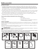
IMPORTANT SAFETY INFORMATION. READ ALL INSTRUCTIONS BEFORE USING. SAFETY PRECAUTIONS WARNING! For your safety, the information in this manual must be followed to minimize the risk of electric shock, property damage or personal injury. DANGER: Electric Shock Hazard: Install metal ground clamp to metal house water supply pipe before beginning installation. Securely tighten connection in center of metal ground clamp. Failure to do so can result in death or electric shock.
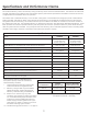
Specifications and Performance Claims. This model is efficiency rated. The efficiency rating is valid only at the minimum stated salt dose. The softener has a demand initiated regeneration (D.I.R) feature that complies with specific performance specifications intended to minimize the amount of regenerant brine and water used in its operation.
About the water softener system. SERVICE When the water softening system is providing soft water, it is called “Service.” During service, hard water flows from the house main water pipe into the water softening system. Inside the water softening system resin tank is a bed made up of thousands of tiny, plastic resin beads. As hard water passes through the bed, each bead attracts and holds the hard minerals. This is called ionexchanging. It is much like a magnet attracting and holding metals.
About the water softener system. NORMAL OPERATION, CONTROL DISPLAYS During normal operation, the present time of day and AM or PM and DAYS TO EMPTY show in the control display area. The system will automatically recharge at the preset recharge time as needed. FEATURE: OPTIONAL RECHARGE CONTROLS RECHARGE TONIGHT Touch (do not hold) the RECHARGE button. RECHARGE TONIGHT flashes in the control display area. A recharge will occur at the next preset recharge start time.
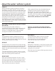
About the water softener system. WATER CONDITION INFORMATION IRON Colloidal and inorganically bound iron is of ferric or ferrous form that will not filter or exchange out of water. This water softener will not remove colloidal iron. In some instances, treatment may improve colloidal iron water. Colloidal iron water usually has a yellow appearance when drawn. After standing for several hours, the color persists and the iron does not settle,but remains suspended in the water.
Before you start. BEFORE YOU START The water softener requires a minimum water flow of 3 gallons per minute at the inlet. Maximum allowable inlet water pressure is 125 psi. If daytime pressure is over 80 psi, nighttime pressure may exceed the maximum. Use a pressure reducing valve if necessary (Adding a pressure reducing valve may reduce the flow). If your home is equipped with a back flow preventer, an expansion tank must be installed in accordance with local codes and laws.
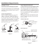
Installation Requirements. LOCATION REQUIREMENTS DO NOT RUN HOT WATER THROUGH THE SOFTENER. Temperature of water passing through the softener must be less than 120° F. Avoid installing in direct sunlight. Excessive sun heat may cause distortion or other damage to non-metallic parts.
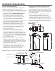
Installation Requirements. PLUMBING CODES VALVE DRAIN REQUIREMENTS All plumbing must be completed in accordance with national, state and local plumbing codes. Using the flexible drain hose (included) (see Figure 2), measure and cut to the length needed. Flexible drain hose is not allowed in all localities (check your plumbing codes). If local codes do not allow use of a flexible drain hose, a rigid valve drain run must be used. Purchase a compression fitting (1/4 NPT x 1/2 in.
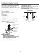
Installation Requirements. INLET/OUTLET PLUMBING REQUIREMENTS Always install either a single bypass valve (provided),as shown in Figure 4, or, if desired, parts for a 3 valve bypass system (not included) can be purchased and assembled, as shown in Figure 5. Bypass valves allow you to turn off water to the softener for maintenance if needed, but still have water in house pipes. Pipe fittings must be 1/2” minimum.
Installation Instructions.
Installation Instructions. TURN OFF WATER SUPPLY 1. Close the main water supply valve, located near the well pump or water meter. 2. Open all faucets to drain all water from house pipes. NOTE: Be sure not to drain water from the water heater, as damage to the water heater elements could result. INSTALL THE BRINE TANK OVERFLOW ADAPTER Install the brine tank overflow grommet and adapter in the 13/16” diameter hole in the back of the salt storage tank sidewall, (see Figure 9).
Installation Instructions. WARNING! COMPLETE INLET AND OUTLET PLUMBING WARNING! ELECTRICAL SHOCK HAZARD: Install metal ground clamp to metal house water supply pipe before beginning installation. Securely tighten connection in center of metal ground clamp. Failure to do so can result in death or electrical shock. Ground Clamp Ground Clamp If solder is used to make pipe connection use only lead free solder and flux to prevent lead poisoning.
Installation Instructions. INSTALL VALVE DRAIN HOSE 1. Measure and connect the 3/8”drain line (provided) to the water softener valve drain fitting. Use a hose clamp to hold the hose in place. NOTE: Avoid drain hose runs longer than 30 feet. Avoid elevating the hose more than 8 feet above the floor. Make the valve drain line as short and direct as possible. IMPORTANT: If codes require a rigid drain line see“Valve Drain requirements” section. 2.
Installation Instructions. ADD WATER AND SALT TO THE SALT STORAGE TANK SANITIZE THE WATER SOFTENER /SANITIZE AFTER SERVICE WARNING! EXCESSIVE WEIGHT HAZARD: Use two or more people to move and lift salt bags. Failure to do so can result in back or other injuries. 1. Using a container, add about three gallons of clean water into the salt storage tank. 2. Add salt to the storage tank. Use nugget, pellet or coarse solar salts with less than 1% impurities. PLUG IN THE WATER SOFTENER 1.
Programming the Water Softener. SET TIME OF DAY When the transformer is plugged into the electrical outlet, a model code and test number (example: J3.4 & H45) are shown in the display. Then, “12:00 PM” begins to flash. An arrow is displayed next to CLOCK on the face plate decal. CONTROL OPERATION: &21752/ 6(77,1*6 5(48,5(' upon initial installation and after an extended power outage. 8VH WKH MODE/SET button to scroll arrow to desired control function set.
Programming the Water Softener. SET WATER HARDNESS NUMBER 1. Press the MODE/SET button until the arrow points to HARDNESS. A flashing 25 will appear in the display. SET RECHARGE (STARTING) TIME 1. Press the MODE/SET button until the arrow points to RECHARGE. Salt Level Clock Hardness Recharge Salt Level Clock Hardness Recharge AM NOTE: A flashing 2:00 AM (factory default) should show in the display.
Programming the Water Softener. SET SALT LEVEL 1. Press the MODE/SET button until the arrow points to SALT LEVEL. Salt Level Clock Hardness Recharge 2. Determine level of salt in brine tank using the numbered scale on side of brine well, inside brine tank (see Figure 15). DAYS TO EMPTY The words DAYS TO EMPTY and a number are shown in the lower half of the display. This information is shown in the normal run display.
Programming the Water Softener. OPTIONAL CONTROL SETTINGS BACKWASH AND FAST RINSE If you experience salty tasting water after regeneration, you may need to increase the backwash and fast rinse times. The cycle times during regenerations are determined by the softener’s electronic controller. However, you may increase the backwash and fast rinse times. You may add up to 10 minutes. The controller display has several options and features.
Programming the Water Softener. FEATURE: OTHER DATA DISPLAY These models have an option to have the run display indicate different information. The information displayed on the top half of the display can be changed or DOWN to one of the following by pressing UP buttons: CAPACITY REMAINING – This is the percentage of water % Remaining softening capacity remaining. Days to Empty Immediately after a regeneration, Recharge Tonight 100% shows.
Programming the Water Softener. POWER OUTAGE MEMORY ERROR SIGNALS If electrical power to the water softener is lost, “memory’’ built into the timer circuitry will keep all settings for up to 24 hours. While the power is out, the display is blank and the water softener will not regenerate. When electrical power is restored, the following will occur: Reset the present time only if the display is flashing. The HARDNESS and RECHARGE TIME never require resetting unless a change is desired.
Care and cleaning. ADJUSTING YOUR WATER HARDNESS SERVICE POSITION The blend adjusting knob (Figure 16) gives the (Normal Softener Operation) ability to finely adjust hardness of the treated water Soft Water leaving the water softener. If slightly harder water Hard Out Pull Water In is desired than is normally delivered by the water Handle softener, the blend adjusting knob can divert a small stream of hard water and blend it with the soft water entering the home.
Care and cleaning. CHECKING THE SALT STORAGE LEVEL and REFILL Brine (salt dissolved in water) is needed for each and every recharge. The water for making brine is metered into the salt storage area by the water softening system valve and control. However, you must keep the tank supplied with salt. ADDING SALT Lift the salt hole cover and check the salt storage level frequently. If the water softener uses all the salt before you refill it, you will experience hard water.
Routine Maintenance. CLEANING THE NOZZLE AND VENTURI ASSEMBLY A clean nozzle and venturi is needed for the water softening system to work properly. This small unit makes the suction to move brine from the salt storage area to the resin tank during recharge. If it becomes plugged with sand, dirt, etc., the water softening system will not work and you will get hard water. To get to the nozzle and venturi, remove the water softening system top cover.
Before you call for service. Troubleshooting Tips Save time and money! Review the chart on this page first and you may not need to call for service.
Before you call for service. Problem Possible Cause What to do Water hard sometimes Using hot water while the water softening system is regenerating $YRLG XVLQJ KRW ZDWHU GXULQJ ZDWHU VRIWHQLQJ system recharge because the water heater will UH¿OO ZLWK KDUG ZDWHU 6HH $XWRPDWLF +DUG :DWHU Bypass During Recharge section. Control HARDNESS number setting too low 3UHVV 02'( 6(7 EXWWRQ XQWLO DUURZ SRLQWV WR HARDNESS.
Before you call for service. Problem Possible Cause What to do Excessive/high level of water in brine tank Valve drain hose pinched, plugged, elevated too high or otherwise restricted $ UHVWULFWLRQ LQ WKLV GUDLQ KRVH PD\ SUHYHQW SURSHU operation of the nozzle and venturi and reduce or prevent brine draw during recharge. Nozzle and venturi dirty, incorrectly assembled or damaged. 5HIHU WR &OHDQLQJ WKH 1R]]OH DQG 9HQWXUL $VVHPEO\ instructions.
Before you call for service. Problem Possible Cause What to do Error Codes on Control Wiring may have worked loose in the control 8QSOXJ H[WHUQDO SRZHU VXSSO\ 5HPRYH FRQWURO FRYHU UHOHDVH FOLSV RQ VLGH &KHFN IRU ORRVH LQFRUUHFW ZLULQJ FRQQHFWLRQV to electronic board or switch. Reconnect as required.
Advanced troubleshooting for service. AUTOMATIC ELECTRONIC DIAGNOSTICS 3. Symbols in the display indicate POSITION switch operation, see Figure 19 This water softener has a self-diagnostic function for the electrical system Call for Service (except into power and/ or water meter). The water softener monitors electronic components and circuits Figure 18 for correct operation. If a malfunction occurs, an error code appears in the display.
Advanced troubleshooting for service. Service: Manually Advance Recharge Check NOTE: The control display must show a steady time (not flashing). 1. Press the RECHARGE button and hold in for three seconds. RECHARGE begins to flash as the water softening system enters the fill cycle of recharge. Remove the brinewell cover and, using a flashlight, observe fill water entering the brine tank. If water does not enter the tank, look for an obstructed nozzle, venturi, fill flow plug or brine tubing.
Exploded View.
Exploded View.
Parts List. REF. NO. GE PART NO.
Parts List. REF. NO. GE PART NO.
GE Water Softening System Warranty.(For Customers in the U.S.) All warranty service provided by our Factory Service Centers or an authorized technician. For service, call toll free 1-800-952-5039. Please have serial number and model number available when calling for service. We Will Replace: For The Period Of: One Year From the date of the original purchase Any part of the Water Softening System which fails due to defect in materials or workmanship.
GE Water Softening System Warranty.(For Customers in Canada) All warranty service provided by our Factory Service Centers or an authorized technician. For service, call toll free 1-866-777-7627. Please have serial number and model number available when calling for service. For The Period Of: We Will Replace: One Year From the date of the original purchase Any part of the Water Softening System which fails due to defect in materials or workmanship.
California certificate.
California certificate.
Notes.
Notes.
Información sobre Seguridad . . . . . . . . . 42 Especificaciones y Dimensiones . . . . . . 43 Acerca del Suavizante . . . . . . . . . . . . . . . . 46 Antes de Comenzar . . . . . . . . . . . . . . . . . . . 47 Requisitos de Instalación . . . . . . . . . . 48-50 Instrucciones de Instalación . . . . . . . 51-55 Programación del Suavizante . . . . . . 56-61 Cuidado y Limpieza . . . . . . . . . . . . . . . .62, 63 Rutina de Mantenimiento . . . . . . . . . . . . . 64 Antes de solicitar el servicio . . . . . . .
INFORMACIÓN IMPORTANTE DE SEGURIDAD. LEA TODAS LAS INSTRUCCIONES ANTES DEL USO. PRECAUCIONES DE SEGURIDAD ¡ADVERTENCIA! Por su seguridad, se debe seguir la información en este manual con el fin de reducir el riesgo de una descarga eléctrica, daños a la propiedad o daños personales. embalaje luego de la instalación. Las pequeñas partes restantes luego de la instalación podrían ocasionar riesgo de Riesgo de Descarga Eléctrica: obstrucción.
Reclamos por Especificaciones y Funcionamiento. Este modelo cuenta con una calificación de eficiencia. El índice de eficiencia es válido sólo con la dosis de sal mínima indicada. El suavizante cuenta con la función de regeneración de demanda iniciada (demand initiated regeneration, D.I.R.), que cumple con las especificaciones de funcionamiento para minimizar la cantidad de salmuera regenerante y agua usada en esta operación.
Sobre el sistema de descalcificación de agua. SERVICIO Después de un período de tiempo, la capa de resina se obstruye o se satura con los minerales duros y debe limpiarse. Esta limpieza se denomina recarga. La recarga comienza a las 2:00 AM (ajustado en fábrica) por el control del sistema de descalcificación de agua, y consiste en cinco etapas o ciclos. Éstas son FILL (llenado), BRINING (proceso de salado), BRINE RINSE (enjuague salado), BACKWASH (lavado regresivo) y FAST RINSE (lavado rápido).
Sobre el sistema de descalcificación de agua. FUNCIONAMIENTO NORMAL, PANTALLAS DE CONTROL Durante el funcionamiento normal, la hora actual del día y AM o PM y DAYS TO EMPTY (DÍAS HASTA VACIARSE) aparecen en el área de la pantalla de control. El sistema se recargará de forma automática en el tiempo de recarga presente, según sea necesario. FUNCIÓN: CONTROLES OPCIONALES DE RECARGADO RECARGAR ESTA NOCHE Presione (sin mantener presionado) el botón RECHARGE (Recargar).
Sobre el sistema de descalcificación de agua. INFORMACIÓN SOBRE LA CONDICIÓN DEL AGUA HIERRO El hierro del agua puede causar manchas en la ropa y accesorios de plomería. Puede alterar de forma negativa el sabor de la comida, el agua potable y otras bebidas. El hierro del agua es medido en partes por millón (ppm). El ppm de hierro total*, y el tipo o tipos* es determinado a través de análisis químicos.
Antes de comenzar. ANTES DE COMENZAR El suavizante de agua requiere un flujo mínimo de agua de 3 galones por minuto en la entrada. La presión de entrada de agua máxima tolerable es de 125 psi. Si la presión del día supera los 80 psi, es posible que la presión nocturna supere el máximo. Si es necesario, utilice una válvula de reducción de presión (agregar una válvula de reducción de presión puede reducir el flujo).
Requisitos de Instalación. REQUISITOS DE UBICACIÓN Considere todo lo siguiente al seleccionar una ubicación de instalación del suavizante de agua. No coloque el suavizante de agua donde haya temperaturas heladas. No intente tratar el agua a más de 120 ºF. Los daños por temperaturas heladas o agua caliente anulan la garantía.
Requisitos de Instalación. CÓDIGOS DE PLOMERÍA Toda la plomería deberá ser completada de acuerdo con los códigos de plomería nacional, estatal y local. En el estado de Massachusetts: En el Commonwealth de Massachusetts, se deberá cumplir con el Código de Plomería 248 CMR. Se deberá contratar a un plomero matriculado para esta instalación. REQUISITOS DE ESPACIO LIBRE Es necesario un drenaje para el agua de regeneración (Ver la Figura 1).
Requisitos de Instalación. REQUISITOS DE PLOMERÍA INTERIOR/ EXTERIOR Siempre instale una válvula de desviación simple (provista), como se muestra en la Figura 4, o, si lo desea, puede adquirir y ensamblar piezas para un sistema de desviación de 3 válvulas (no incluido), como se muestra en la Figura 5. Las válvulas de desviación le permiten cerrar el agua en el suavizante para el mantenimiento si es necesario, pero aún tener agua en las tuberías de la casa.
Instrucciones de Instalación.
Instrucciones de Instalación. CIERRE EL SUMINISTRO DE AGUA 1. Cierre la válvula del suministro principal de agua, ubicada cerca de la bomba del pozo o del medidor de agua. 2. Abra todos los grifos para drenar toda el agua de las tuberías de la casa. NOTA: Asegúrese de no drenar el agua del calentador de agua, ya que esto podría ocasionar daños sobre los elementos del calentador de agua.
Instrucciones de Instalación. ¡ADVERTENCIA! COMPLETE LA PLOMERÍA DE ENTRADA Y SALIDA ¡ADVERTENCIA! Si se harán soldaduras para la conexión de las tuberías, use sólo soldadoras y fundidores libres de plomo para evitar el envenenamiento con plomo. RIESGO DE DESCARGA ELÉCTRICA: Instale una clavija de metal con conexión a tierra a la tubería metálica del suministro de agua del hogar antes de comenzar la instalación.
Instrucciones de Instalación. INSTALE LA MANGUERA DE DRENAJE DE LA VÁLVULA 1. Mida y conecte la línea de drenaje de 3/8” (provista) al accesorio de drenaje de la válvula del suavizante de agua. Use un sujetador de manguera para sostener la misma en su lugar. NOTA: Evite que la manguera de drenaje supere los 30 pies. Evite elevar la manguera más de 8 pies sobre el piso. Haga que la línea de drenaje con válvula sea tan corta y directa como sea posible.
Instrucciones de Instalación. AGREGUE AGUA Y SAL AL TANQUE DE ALMACENAMIENTO DE SAL DESINFECTE EL SUAVIZANTE DE AGUA/ DESINFECTE LUEGO DEL SERVICIO 1. Abra la tapa del agujero de sal, retire la tapa del pozo de salmuera y vierta alrededor de 3 oz. (6 cucharones) de blanqueador de hogar en el pozo de salmuera del suavizante. Reemplace la tapa del pozo de salmuera. 2. Asegúrese de que la válvula(s) de desviación esté en la posición de “servicio” (abierta). 3. Comience una recarga (regeneración).
Programación del Suavizante de Agua. CONFIGURE LA HORA DEL DÍA Cuando el transformador está enchufado en el tomacorriente eléctrico, un código de modelo y número de evaluación (ejemplo: J3.4 & H45) aparecen en la pantalla. Luego, “12:00 PM” comienza a titilar. Una flecha aparece junto a CLOCK (Reloj) en la calcomanía de la placa. FUNCIONAMIENTO DEL CONTROL: &21),*85$&,21(6 '( &21752/ 5(48(5,'$6 en la instalación inicial y luego de un corte de corriente prolongado.
Programación del Suavizante de Agua. CONFIGURE EL NÚMERO DE DUREZA DEL AGUA CONFIGURACIÓN DEL TIEMPO (INICIAL) DE RECARGA 1. Presione el botón MODE/SET (Modo/ apunte a Configuración) hasta que la flecha HARDNESS (Dureza). Un 25 titilante aparecerá en la pantalla. 1. Presione el botón MODE/SET (Modo/ Configuración) hasta que la flecha RECHARGE (Recargar). Salt Level Clock Hardness Recharge Salt Level Clock Hardness Recharge o DOWN 2.
Programación del Suavizante de Agua. CONFIGURE EL NIVEL DE SAL 1. Presione el botón MODE/SET (Modo/ Configuración) hasta que la flecha apunte a SALT LEVEL (Nivel de Sal). Salt Level Clock Hardness Recharge 2. Determine el nivel de sal en el tanque de salmuera usando la escala numerada al costado del pozo de salmuera, dentro del tanque de salmuera (vea la Figura 15). 3.
Programación del Suavizante de Agua. CONFIGURACIONES OPCIONALES DEL CONTROL LAVADO REGRESIVO Y ENJUAGUE RÁPIDO La pantalla del controlador cuenta con varias opciones y funciones. Si siente que el sabor del agua es salado luego de la regeneración, es posible que necesite incrementar los tiempos del lavado regresivo y de enjuague rápido. Los tiempos de los ciclos durante las regeneraciones son determinados por el controlador electrónico del suavizante.
Programación del Suavizante de Agua. FUNCIÓN: PANTALLA DE OTROS DATOS REAJUSTE A FALTA DE FÁBRICA CAPACIDAD RESTANTE 1. Mantenga presionado el botón MODE/SET (Modo/ Configuración) hasta que la pantalla cambie dos veces y muestre el código del modo titilante. Estos modelos tienen una opción para que la pantalla indique información diferente. La información mostrada en la mitad superior de la pantalla puede ser modificada a una de las siguientes presionando los botones UP (Arriba) o DOWN (Abajo).
Programación del Suavizante de Agua. MEMORIA POR CORTE DE CORRIENTE SEÑAL DE NIVEL DE SAL BAJO Si se corta la corriente del suavizante de agua, la “memoria” incorporada en los circuitos del temporizador mantendrán todas las configuraciones durante hasta 24 horas. Mientras la corriente esté cortada, la pantalla quedará en blanco y el suavizante de agua no se regenerará. Cuando la corriente eléctrica sea restablecida, ocurrirá lo siguiente.
Cuidado y limpieza. AJUSTE DE LA DUREZA DEL AGUA La perilla de ajuste de mezcla (Figura 16) le da la posibilidad de ajustar finamente la dureza del agua tratada, dejando el suavizante de agua. Si se desea un agua un poco más dura que aquella normalmente provista por el suavizante de agua, la perilla de ajuste de mezcla puede desviar un pequeño flujo de agua dura y mezclar ésta con el agua suave que entra al hogar.
Cuidado y limpieza. CONTROL DEL NIVEL DE ALMACENAMIENTO DE SAL y RECARGA La salmuera (sal disuelta en agua) es necesaria en cada recarga. El agua para hacer salmuera es medida en el área de almacenamiento de sal por la válvula del sistema suavizante de agua y el control. Sin embargo, se deberá mantener el tanque suministrado con sal. AGREGADO DE SAL Levante la tapa del agujero de sal y controle el nivel de almacenamiento de sal de forma frecuente.
Rutina de Mantenimiento. LIMPIEZA DEL ENSAMBLE DE LA BOQUILLA Y EL VENTURI Tapa Una limpieza de la boquilla y el venturi es necesaria para que el sistema suavizante funcione de forma correcta. Esta pequeña unidad hace que la succión mueva la salmuera del área de almacenamiento de sal al tanque de resina durante la recarga. Si se tapa con arena, tierra, etc., el sistema suavizante de agua no funcionará y se generará agua dura.
Antes de solicitar el servicio técnico. ¡Los Consejos para la Solución de Problemas le Permiten Ahorrar tiempo y dinero! Lea primero el cuadro que aparece en esta página y es posible que no necesite solicitar el servicio técnico. NO HAY AGUA SUAVE – Problemas Más Comunes: Realice el control antes de llamar al servicio técnico: No hay suficiente sal – deberá estar en por lo menos 1/3. Válvula de desviación en la posición “Desviación” – la manija debería estar en la posición “OUT” (Fuera) (servicio).
Antes de solicitar el servicio técnico. Problema Causa Posible Qué hacer Agua dura a veces Uso de agua caliente mientras el sistema suavizante de agua se está regenerando (YLWH XVDU DJXD FDOLHQWH GXUDQWH OD UHFDUJD GHO sistema suavizante de agua, ya que el calentador de agua se volverá a llenar con agua dura.
Antes de solicitar el servicio técnico. Problema Causa Posible Qué hacer Nivel excesivo/alto de agua en el tanque de salmuera La válvula de la manguera de drenaje está pinzada, atascada, demasiado elevada o de algún modo restringida &XDOTXLHU UHVWULFFLyQ HQ OD PDQJXHUD GH GUHQDMH podrá impedir un funcionamiento correcto de la boquilla y el venturi y reducir o impedir el ingreso de salmuera durante la recarga.
Antes de solicitar el servicio técnico. Problema Causa Posible Qué hacer Códigos de Error en el Control Es posible que el cableado se haya DÀRMDGR HQ HO FRQWURO 'HVHQFKXIH HO VXPLQLVWUR GH FRUULHQWH H[WHUQR 5HWLUH OD WDSD GHO FRQWURO OLEHUH ORV VXMHWDGRUHV DO costado. &RQWUROH TXH QR KD\D FRQH[LRQHV GH FDEOHV VXHOWRV incorrectas al tablero electrónico o interruptor. Vuelva a conectar según se requiera.
Solución de problemas avanzados para el servicio técnico. DIAGNÓSTICO ELECTRÓNICO AUTOMÁTICO Este suavizante de agua cuenta con una función de auto diagnóstico del sistema eléctrico (excepto para la corriente Call for Service y/o el medidor de agua). El suavizante de agua monitorea que los componentes y Figura 18 circuitos electrónicos funcionen correctamente. Si se produce un mal funcionamiento, se visualizará un código de error en la pantalla.
Solución de problemas avanzados para el servicio técnico. Servicio: Control de Recarga Avanzado en forma Manual NOTA: La pantalla de control debe mostrar el horario de manera fija (no titilando). 1. Presione el botón RECHARGE (Recarga) y manténgalo presionado por tres segundos. RECHARGE (Recarga) comienza a titilar a medida que el sistema suavizante ingresa al ciclo de llenado de la recarga. Retire la tapa del pozo de salmuera y, usando una linterna, observe el agua al ingresar al tanque de salmuera.
Vista Expandida.
Vista Expandida.
Listado de Piezas. REF. NO. GE PART NO.
Listado de Piezas. REF. NO. GE PART NO.
Garantía del Sistema Suavizante de Agua de GE.(Para clientes en EE.UU.) Todo el servicio de garantía es provisto por nuestros Centros de Servicio de Fabricación, o un técnico autorizado. Para solicitar el servicio técnico, llame al número gratuito 1-800-952-5039. Cuando llame para solicitar el servicio, tenga los números de serie y modelo disponibles. Por el Período de: Reemplazaremos: Un Año Desde la fecha de compra original.
Garantía del Sistema Suavizante de Agua de GE.(Para Clientes en Canadá) Todo el servicio de garantía es provisto por nuestros Centros de Servicio de Fabricación, o un técnico autorizado. Para solicitar el servicio técnico, llame al número gratuito 1-866-777-7627. Cuando llame para solicitar el servicio, tenga los números de serie y modelo disponibles. Por el Período de: Reemplazaremos: Un Año Desde la fecha de compra original.
Certificado de California.
Certificado de California.
Soporte al Consumidor. Página Web de GE Appliances GEAppliances.com ¿Tiene alguna pregunta sobre su electrodoméstico? ¡Pruebe la página Web de GE Appliances 24 horas al día, cualquier día del año! Para mayor conveniencia y servicio más rápido, ya puede descargar los Manuales de los Propietarios o pedir piezas en línea. Solicite una reparación GEAppliances.com El servicio de expertos GE está a tan sólo un paso de su puerta. Llame al 800.GE.CARES (800.432.
Consumer Support. GE Appliances Website GEAppliances.com Have a question or need assistance with your appliance? Try the GE Appliances Website 24 hours a day, any day of the year! For greater convenience and faster service, you can now download Owner’s Manuals or order parts online. Schedule Service GEAppliances.com Expert GE repair service is only one step away from your door. Schedule your service at your convenience by calling 800.GE.CARES (800.432.2737) during normal business hours.