
Product Manual

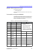
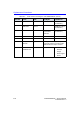
Table Of Contents
- Vivid™ E80 / Vivid™ E90 / Vivid™ E95
- Table of Contents
- Chapter 1
- Introduction
- Chapter 2
- Site Preparations
- General Ultrasound system requirements
- Facility needs
- Environmental Dangers
- Chapter 3
- System Setup
- Setup reminders
- Receiving and unpacking the equipment
- Packing materials - recycling information
- Preparing for setup
- Completing the setup
- Configuration
- Connectivity overview
- Connectivity setup
- Product Locator Installation Card
- Chapter 4
- General Procedures and Functional Checks
- Chapter 5
- Components and Functions (Theory)
- Software overview
- InSite ExC
- Vivid E80/E90/E95 overview
- Top Console with LCD monitor and Operating Panel
- Main Console
- Air Flow control
- Casters and brakes
- Front End Processor (FEP)
- Back End Processor (BEP)
- Power distribution
- Input and Output (I/O) modules
- Restart Vivid E80/E90/E95 after diagnostics
- Chapter 6
- Service Adjustments
- Chapter 7
- Diagnostics/Troubleshooting
- Chapter 8
- Replacement Procedures
- Warnings and important information
- Loading the software
- Replacing covers and bumpers
- LCD Monitor and LCD Arm parts replacement
- Upper OP Panel/Touch Panel Assembly replacement
- Lower Operating Panel Parts replacement
- A/N Keyboard parts replacement
- Other Top Console Parts replacement
- Replacing XYZ Parts
- Main Console parts replacement
- Casters and Brakes replacement
- Front End Processor (FEP) / Card Cage parts replacement
- Back End Processor (BEP) parts replacement
- Main Power Supply replacement
- Patient I/O assembly replacement
- Peripherals replacement
- Cables replacement
- Chapter 9
- Renewal Parts
- List of Abbreviations
- Software for Vivid E80/E90/E95
- Covers and Bumpers
- Top Console parts
- XYZ parts
- Main Console parts
- Casters (wheels) parts
- Front End Processor (FEP) Card Rack parts
- Back End Processor (BEP) parts
- Main Power Supply
- I/O modules parts
- Peripherals for use with Vivid E80/ E90/E95
- Mains power cables - Vivid E80/E90/ E95
- Internal Cables - Vivid E80/E90/E95
- ECG cables - Vivid E80/E90/E95
- Physio TX parts
- Probes for Vivid E80/E90/E95
- Options - Vivid E80/E90/E95
- Chapter 10
- Care and Maintenance
- Index

Warnings and important information
Vivid E80/E90/E95 – Service Manual 8-5
GC091052 Rev. 3
Manpower - When two persons are needed
Two persons are required for:
• Casters Replacement
The rest of the replacement procedures can be carried out by
one person.
Tools needed for servicing Vivid E80/E90/E95
The following tools (TORX bits or drivers) are needed to service
the Ultrasound system. Screw diameter and standard torque
values are also included. If the torque is not indicated with the
procedure, hand tighten the screws/nuts.
Table 8-1: Tools used for servicing the Vivid E80/E90/E95
ITEM NO. TOOL SIZE TORQUE COMMENTS
1.
BIT # TX-10 M2.5 • Use Torque specified in
procedure.
• If the torque is not indicated
with the procedure, hand
tighten the screws / nuts.
• 90 degree “L” are suggested.
• A full set of 90 degree “L” TORX
wrenches are recommended.
2.
BIT # TX-15 M3
3.
BIT # TX-20 M4
4.
BIT # TX-25 M5
5.
BIT # TX-30 M6
6.
BIT # TX-45 M10
7.
FLAT BLADE
DRIVER
3.2 mm
8.
FLAT BLADE
DRIVER
4 mm
9.
FLAT BLADE
DRIVER
6 mm
10.
PHILLIPS
DRIVER
PH1
11.
PHILLIPS
DRIVER
PH2
12.
PHILLIPS
DRIVER
PH3
13.
HEX KEY 5 mm (Unbrako Key /
Allen Key)