
Product Manual
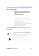
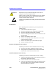
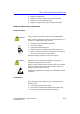
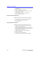
Table Of Contents
- Vivid™ E80 / Vivid™ E90 / Vivid™ E95
- Table of Contents
- Chapter 1
- Introduction
- Chapter 2
- Site Preparations
- General Ultrasound system requirements
- Facility needs
- Environmental Dangers
- Chapter 3
- System Setup
- Setup reminders
- Receiving and unpacking the equipment
- Packing materials - recycling information
- Preparing for setup
- Completing the setup
- Configuration
- Connectivity overview
- Connectivity setup
- Product Locator Installation Card
- Chapter 4
- General Procedures and Functional Checks
- Chapter 5
- Components and Functions (Theory)
- Software overview
- InSite ExC
- Vivid E80/E90/E95 overview
- Top Console with LCD monitor and Operating Panel
- Main Console
- Air Flow control
- Casters and brakes
- Front End Processor (FEP)
- Back End Processor (BEP)
- Power distribution
- Input and Output (I/O) modules
- Restart Vivid E80/E90/E95 after diagnostics
- Chapter 6
- Service Adjustments
- Chapter 7
- Diagnostics/Troubleshooting
- Chapter 8
- Replacement Procedures
- Warnings and important information
- Loading the software
- Replacing covers and bumpers
- LCD Monitor and LCD Arm parts replacement
- Upper OP Panel/Touch Panel Assembly replacement
- Lower Operating Panel Parts replacement
- A/N Keyboard parts replacement
- Other Top Console Parts replacement
- Replacing XYZ Parts
- Main Console parts replacement
- Casters and Brakes replacement
- Front End Processor (FEP) / Card Cage parts replacement
- Back End Processor (BEP) parts replacement
- Main Power Supply replacement
- Patient I/O assembly replacement
- Peripherals replacement
- Cables replacement
- Chapter 9
- Renewal Parts
- List of Abbreviations
- Software for Vivid E80/E90/E95
- Covers and Bumpers
- Top Console parts
- XYZ parts
- Main Console parts
- Casters (wheels) parts
- Front End Processor (FEP) Card Rack parts
- Back End Processor (BEP) parts
- Main Power Supply
- I/O modules parts
- Peripherals for use with Vivid E80/ E90/E95
- Mains power cables - Vivid E80/E90/ E95
- Internal Cables - Vivid E80/E90/E95
- ECG cables - Vivid E80/E90/E95
- Physio TX parts
- Probes for Vivid E80/E90/E95
- Options - Vivid E80/E90/E95
- Chapter 10
- Care and Maintenance
- Index

Replacement Procedures
8-62 Vivid E80/E90/E95 – Service Manual
GC091052
Rev. 3
4. Remove the Rotary buttons below the Touch screen and the
Volume button.
5. Remove the Operating Panel, Upper.
6. Remove the Operating Panel, Lower. Place it on a clean
surface with the front down.
7. Remove Handle Left Top and Handle Right Top.
8. Remove the Palm Rest Cover.
Remove the Button IF Board Assy
Follow this procedure to remove the Button IF Board Assy
1. Disconnect all the five (5x) connectors from the board.
2. Push the TABs away to release the board.
3. Remove the board.
Install the Button IF Board Assy
Follow this procedure to install the Button IF Board Assy
1. Install the Button IF Board into the UI Frame, Lower by
pressing it under the small hooks.
2. Ensure the XYZ Buttons Frame cable runs along the Lower
Op Panel cable channel so that the cable is not pinched
when the Palm Rest is replaced.
3. Install the Handle Left Top and Handle Right Top.
4. Replace the Palm Rest.
5. Replace the Lower Operating Panel.
6. Replace the Upper OP Panel/Touch Panel assembly.