
Product Manual

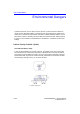


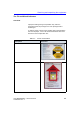
Table Of Contents
- Vivid™ E80 / Vivid™ E90 / Vivid™ E95
- Table of Contents
- Chapter 1
- Introduction
- Chapter 2
- Site Preparations
- General Ultrasound system requirements
- Facility needs
- Environmental Dangers
- Chapter 3
- System Setup
- Setup reminders
- Receiving and unpacking the equipment
- Packing materials - recycling information
- Preparing for setup
- Completing the setup
- Configuration
- Connectivity overview
- Connectivity setup
- Product Locator Installation Card
- Chapter 4
- General Procedures and Functional Checks
- Chapter 5
- Components and Functions (Theory)
- Software overview
- InSite ExC
- Vivid E80/E90/E95 overview
- Top Console with LCD monitor and Operating Panel
- Main Console
- Air Flow control
- Casters and brakes
- Front End Processor (FEP)
- Back End Processor (BEP)
- Power distribution
- Input and Output (I/O) modules
- Restart Vivid E80/E90/E95 after diagnostics
- Chapter 6
- Service Adjustments
- Chapter 7
- Diagnostics/Troubleshooting
- Chapter 8
- Replacement Procedures
- Warnings and important information
- Loading the software
- Replacing covers and bumpers
- LCD Monitor and LCD Arm parts replacement
- Upper OP Panel/Touch Panel Assembly replacement
- Lower Operating Panel Parts replacement
- A/N Keyboard parts replacement
- Other Top Console Parts replacement
- Replacing XYZ Parts
- Main Console parts replacement
- Casters and Brakes replacement
- Front End Processor (FEP) / Card Cage parts replacement
- Back End Processor (BEP) parts replacement
- Main Power Supply replacement
- Patient I/O assembly replacement
- Peripherals replacement
- Cables replacement
- Chapter 9
- Renewal Parts
- List of Abbreviations
- Software for Vivid E80/E90/E95
- Covers and Bumpers
- Top Console parts
- XYZ parts
- Main Console parts
- Casters (wheels) parts
- Front End Processor (FEP) Card Rack parts
- Back End Processor (BEP) parts
- Main Power Supply
- I/O modules parts
- Peripherals for use with Vivid E80/ E90/E95
- Mains power cables - Vivid E80/E90/ E95
- Internal Cables - Vivid E80/E90/E95
- ECG cables - Vivid E80/E90/E95
- Physio TX parts
- Probes for Vivid E80/E90/E95
- Options - Vivid E80/E90/E95
- Chapter 10
- Care and Maintenance
- Index

Environmental Dangers
Vivid E80/E90/E95 – Service Manual 2-19
GC091052 Rev. 3
Patient Environment IEC60601-1 (IEC60601-1-1) and ANSI AAMI
ES60601-1
Figure 2-5. Patient environment
Sub Clause 2.202 and figure 201 (IEC60601-1-1:2000)
Sub Clause 3.79 and figure A.9 (IEC60601-1:2005 and ANSI AAMI
ES60601-1:2005)
Such an area is an environment in which medical diagnosis, monitoring or treatment is
carried out. It is very difficult to attach unique dimensions to the PATIENT
ENVIROMENT.
In practice a distance of 2,5 m (8.2 ft.) above the floor on which the medical personnel
stand and a horizontal distance of 1,5 m (4.9 ft.) have justified themselves as
indicative of the dimensions of the Patient Environment.
The patient environment/vicinity will be depicted as a dashed line in this procedure.
See example below.
1. Patient environment