
Product Manual
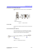
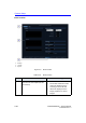
Table Of Contents
- Vivid™ E80 / Vivid™ E90 / Vivid™ E95
- Table of Contents
- Chapter 1
- Introduction
- Chapter 2
- Site Preparations
- General Ultrasound system requirements
- Facility needs
- Environmental Dangers
- Chapter 3
- System Setup
- Setup reminders
- Receiving and unpacking the equipment
- Packing materials - recycling information
- Preparing for setup
- Completing the setup
- Configuration
- Connectivity overview
- Connectivity setup
- Product Locator Installation Card
- Chapter 4
- General Procedures and Functional Checks
- Chapter 5
- Components and Functions (Theory)
- Software overview
- InSite ExC
- Vivid E80/E90/E95 overview
- Top Console with LCD monitor and Operating Panel
- Main Console
- Air Flow control
- Casters and brakes
- Front End Processor (FEP)
- Back End Processor (BEP)
- Power distribution
- Input and Output (I/O) modules
- Restart Vivid E80/E90/E95 after diagnostics
- Chapter 6
- Service Adjustments
- Chapter 7
- Diagnostics/Troubleshooting
- Chapter 8
- Replacement Procedures
- Warnings and important information
- Loading the software
- Replacing covers and bumpers
- LCD Monitor and LCD Arm parts replacement
- Upper OP Panel/Touch Panel Assembly replacement
- Lower Operating Panel Parts replacement
- A/N Keyboard parts replacement
- Other Top Console Parts replacement
- Replacing XYZ Parts
- Main Console parts replacement
- Casters and Brakes replacement
- Front End Processor (FEP) / Card Cage parts replacement
- Back End Processor (BEP) parts replacement
- Main Power Supply replacement
- Patient I/O assembly replacement
- Peripherals replacement
- Cables replacement
- Chapter 9
- Renewal Parts
- List of Abbreviations
- Software for Vivid E80/E90/E95
- Covers and Bumpers
- Top Console parts
- XYZ parts
- Main Console parts
- Casters (wheels) parts
- Front End Processor (FEP) Card Rack parts
- Back End Processor (BEP) parts
- Main Power Supply
- I/O modules parts
- Peripherals for use with Vivid E80/ E90/E95
- Mains power cables - Vivid E80/E90/ E95
- Internal Cables - Vivid E80/E90/E95
- ECG cables - Vivid E80/E90/E95
- Physio TX parts
- Probes for Vivid E80/E90/E95
- Options - Vivid E80/E90/E95
- Chapter 10
- Care and Maintenance
- Index

System Setup
3-20 Vivid E80/E90/E95 – Service Manual
GC091052
Rev. 3
Connections on the I/O Rear Panel
NOTE: Accessory equipment connected to the analog and digital
interfaces must be certified according to the respective IEC
standards (e.g. IEC60950 for data processing equipment and
IEC60601-1 for medical equipment). Furthermore, all complete
configurations shall comply with the valid version of the system
standard IEC60601-1-1. Everybody who connects additional
equipment to the signal input part or signal output part of Vivid
E80/E90/E95, configures a medical system, and is therefore
responsible that the Ultrasound system complies with the
requirements of the valid version of IEC60601-1-1. If in doubt,
consult the technical service department or your local
representative for GE.
Connect Ethernet
Connect the network cable to the Ethernet connector on the I/O
Rear Panel.
The connector is located on the rear side of Vivid E80/E90/E95.
Connect USB Flash Card
NOTE: Only approved USB Flash Cards must be used. USB Flash
Cards approved for Vivid E80/E90/E95 are verified for EMC
performance according to EN55011 class B. The use of any
other USB Flash Cards will compromise this verification, and
may cause interference on Vivid E80/E90/E95 itself, or on other
electronic devices.
For approved models, please refer to Chapter 9.
Install the USB Flash Card in one of the USB ports on the Vivid
E80/E90/E95.