
Product Manual
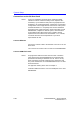
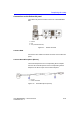
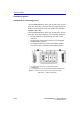
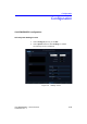
Table Of Contents
- Vivid™ E80 / Vivid™ E90 / Vivid™ E95
- Table of Contents
- Chapter 1
- Introduction
- Chapter 2
- Site Preparations
- General Ultrasound system requirements
- Facility needs
- Environmental Dangers
- Chapter 3
- System Setup
- Setup reminders
- Receiving and unpacking the equipment
- Packing materials - recycling information
- Preparing for setup
- Completing the setup
- Configuration
- Connectivity overview
- Connectivity setup
- Product Locator Installation Card
- Chapter 4
- General Procedures and Functional Checks
- Chapter 5
- Components and Functions (Theory)
- Software overview
- InSite ExC
- Vivid E80/E90/E95 overview
- Top Console with LCD monitor and Operating Panel
- Main Console
- Air Flow control
- Casters and brakes
- Front End Processor (FEP)
- Back End Processor (BEP)
- Power distribution
- Input and Output (I/O) modules
- Restart Vivid E80/E90/E95 after diagnostics
- Chapter 6
- Service Adjustments
- Chapter 7
- Diagnostics/Troubleshooting
- Chapter 8
- Replacement Procedures
- Warnings and important information
- Loading the software
- Replacing covers and bumpers
- LCD Monitor and LCD Arm parts replacement
- Upper OP Panel/Touch Panel Assembly replacement
- Lower Operating Panel Parts replacement
- A/N Keyboard parts replacement
- Other Top Console Parts replacement
- Replacing XYZ Parts
- Main Console parts replacement
- Casters and Brakes replacement
- Front End Processor (FEP) / Card Cage parts replacement
- Back End Processor (BEP) parts replacement
- Main Power Supply replacement
- Patient I/O assembly replacement
- Peripherals replacement
- Cables replacement
- Chapter 9
- Renewal Parts
- List of Abbreviations
- Software for Vivid E80/E90/E95
- Covers and Bumpers
- Top Console parts
- XYZ parts
- Main Console parts
- Casters (wheels) parts
- Front End Processor (FEP) Card Rack parts
- Back End Processor (BEP) parts
- Main Power Supply
- I/O modules parts
- Peripherals for use with Vivid E80/ E90/E95
- Mains power cables - Vivid E80/E90/ E95
- Internal Cables - Vivid E80/E90/E95
- ECG cables - Vivid E80/E90/E95
- Physio TX parts
- Probes for Vivid E80/E90/E95
- Options - Vivid E80/E90/E95
- Chapter 10
- Care and Maintenance
- Index

System Setup
3-22 Vivid E80/E90/E95 – Service Manual
GC091052
Rev. 3
Connecting probes
Introduction to ‘Connecting probes’
The Vivid E80/E90/E95 has three types of probe ports; one PD
probe port, three PDT probe ports and one Doppler probe port.
Probes can be connected at any time, whether the Vivid E80/
E90/E95 is On or Off.
The Vivid E80/E90/E95 has three types of probe ports; one PD
probe port, three PDT probe ports and one Doppler probe port.
• The PD probe port is compatible with the Vivid 7 probe
connectors.
• The three PDT probe ports are specific to the Vivid E80/
E90/E95 probe connectors.
• The Doppler probe port is used for CW Doppler probes
(non-sector-probes), sometimes called PEDOF probes.
Figure 3-3. Probe connectors
1. PD PROBE PORT: FOR VIVID 7 COMPATIBLE PROBE
CONNECTORS
2. PDT PROBE PORT: FOR Vivid E9 SPECIFIC PROBE CONNECTORS
NOTE! The DOPPLER probe connector is not illustrated in this figure.