
Product Manual
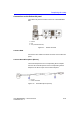
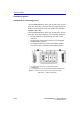
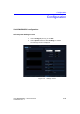
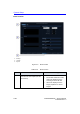
Table Of Contents
- Vivid™ E80 / Vivid™ E90 / Vivid™ E95
- Table of Contents
- Chapter 1
- Introduction
- Chapter 2
- Site Preparations
- General Ultrasound system requirements
- Facility needs
- Environmental Dangers
- Chapter 3
- System Setup
- Setup reminders
- Receiving and unpacking the equipment
- Packing materials - recycling information
- Preparing for setup
- Completing the setup
- Configuration
- Connectivity overview
- Connectivity setup
- Product Locator Installation Card
- Chapter 4
- General Procedures and Functional Checks
- Chapter 5
- Components and Functions (Theory)
- Software overview
- InSite ExC
- Vivid E80/E90/E95 overview
- Top Console with LCD monitor and Operating Panel
- Main Console
- Air Flow control
- Casters and brakes
- Front End Processor (FEP)
- Back End Processor (BEP)
- Power distribution
- Input and Output (I/O) modules
- Restart Vivid E80/E90/E95 after diagnostics
- Chapter 6
- Service Adjustments
- Chapter 7
- Diagnostics/Troubleshooting
- Chapter 8
- Replacement Procedures
- Warnings and important information
- Loading the software
- Replacing covers and bumpers
- LCD Monitor and LCD Arm parts replacement
- Upper OP Panel/Touch Panel Assembly replacement
- Lower Operating Panel Parts replacement
- A/N Keyboard parts replacement
- Other Top Console Parts replacement
- Replacing XYZ Parts
- Main Console parts replacement
- Casters and Brakes replacement
- Front End Processor (FEP) / Card Cage parts replacement
- Back End Processor (BEP) parts replacement
- Main Power Supply replacement
- Patient I/O assembly replacement
- Peripherals replacement
- Cables replacement
- Chapter 9
- Renewal Parts
- List of Abbreviations
- Software for Vivid E80/E90/E95
- Covers and Bumpers
- Top Console parts
- XYZ parts
- Main Console parts
- Casters (wheels) parts
- Front End Processor (FEP) Card Rack parts
- Back End Processor (BEP) parts
- Main Power Supply
- I/O modules parts
- Peripherals for use with Vivid E80/ E90/E95
- Mains power cables - Vivid E80/E90/ E95
- Internal Cables - Vivid E80/E90/E95
- ECG cables - Vivid E80/E90/E95
- Physio TX parts
- Probes for Vivid E80/E90/E95
- Options - Vivid E80/E90/E95
- Chapter 10
- Care and Maintenance
- Index

Completing the setup
Vivid E80/E90/E95 – Service Manual 3-23
GC091052 Rev. 3
Connect a probe
NOTE: It is not necessary to turn OFF power to connect or disconnect a
probe.
Follow these steps to connect a probe:
1. Before connecting the probe:
a. Do a visual check of the probe pins and Ultrasound
system sockets.
b. Remove any dust or foam remains from the probe pins.
c. Inspect the probe and the probe cable for any visual
damage.
2. Hold the probe connector vertically with the cable pointing
upward.
3. Turn the connector locking handle counter-clockwise to the
horizontal position.
4. Align the connector with the probe port and carefully push
into place.
5. Turn the locking handle clockwise to the full vertical position
to lock in place.
6. Position the probe cable so that it is not resting on the floor.
CAUTION
Do not allow the probe head to hang freely. Excessive impact
to the probe will result in irreparable damage.
CAUTION
To prevent probe connector pins damage, or PCB board
damage, do not use excessive force when connecting the
probes.
CAUTION
Keep the probe cables away from the wheels.
Do not bend the probe cables.
Do not cross cables between probes.