
Installation Guide

Installation Instructions
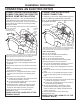
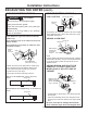
SIDE OR BOTTOM VENTING
Disconnect dryer from electrical supply.
Wear gloves and arm guards.
Close the back opening with cover plate (Kit
WE49X22606).
Failure to do so may result in fire, electrical
shock or lacerations.
WARNING
Fire Hazard
- Fire Hazard
WARNING
15
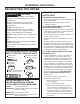
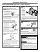
SIDE OR BOTTOM VENTING (cont.)
Dryer Exhaust to right of the cabinet for Electric
models only.
Dryer Exhaust to left of the cabinet for Gas and
Electric models.
Dryer Exhaust to the bottom of cabinet for Gas
and Electric models.
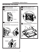
Detach and remove the right (electric models only),
left or bottom knockout as desired. Remove the
screw inside the dryer exhaust duct and save.
Pull the duct out of the dryer.
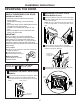
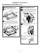
Cut the duct as shown and keep portion A.
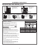
ADDING A NEW DUCT
Reconnect the cut portion (A) of the duct to the blower
housing. Make sure that the shortened duct is aligned
with the tab in the base. Use the screw saved previously
to secure the duct in place through the tab on the
appliance base.
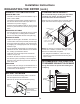
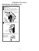
ADDING ELBOW AND DUCT FOR
EXHAUST TO RIGHT (ELECTRIC
MODELS ONLY) OR LEFT SIDE OF
CABINET
• Preassemble 4” elbow with 4” duct. Wrap duct tape
around joint.
• Insert duct assembly, elbow first, through the side
opening and connect the elbow to the dryer internal
duct.
Be sure not to pull or damage the electrical
wires inside the dryer when inserting the duct.
TAB LOCATION
Remove
screw
and save
Remove desired
knockout (one only)
Right
(electric
models
only)
Left
Bottom
Through the rear opening, locate the tab in the middle
of the appliance base. Lift the tab to about 45°,
using
a flat-blade screwdriver.
Portion “A”
Right (electric
models only)
or left side
exhaust
Fixing hole
Left
Right
Exhaust can be
added to right
(electric models
only) or left side
Duct
tape
Right
Left
Bend tab
up 45°
Not for gas models
Left
EXHAUSTING THE DRYER (cont.)
Fixing hole
A
10
1
⁄2” (26.67cm)
For 7.4 cu. ft. models only, use the dimension
below:
Fixing hole
A
9
1
⁄2” (24.13cm)
For 6.2 and 7.2 cu. ft. models only, use the dimension
below: