ge.com Safety Instructions ........ 2, 3 Operating Instructions Light Controls ............... Vent (',ontrols 4 4 ............... ./17935 jq7936 0 fV965 Care and Cleaning Grease Fihers ................ 5 Hood Lights ................ Hood Surfaces ............... Stainless Steel Surfaces ........ 6 5 5 Installation Instru,_tions Troubleshooting Tips ...7-18 ....... Consumer Support Consumer Support... Product Registration _'arranty .................. jq7966 20 Back Cover ......
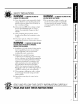
IMPORTANTSAFETYINFORMATION. READALLINSTRUCTIONSBEFOREUSING. \ I"(! " SAFETY PRECAUTIONS WARNING-TO REDUCE THE RISK OF FIRE,WARNING - To REOUCE THE RISK OF ELECTRIC SHOCKORINJURY TOPERSONS, OBSERVETHEFOLLOWING: INJURYTOPERSONSIN THEEVENTOFA RANGE TOPGREASEFIRE,OBSERVETHEFOLLOWING*: .at. Use this unit onl} in the re;tuner A. SMOTHER HAMES _a_th a close-fitting lid, cookie sheet or metal tlW, then turll off the burner BE CAREFUI_ TO PREVENT intended by the manui_mturer.
ge.com SAFETY PRECAUtiONS WARNING- To REDUCETHERISKOF WARNING - ToREDUCE THE RISK OF FIRE, A RANGETOPGREASEFIRE." USEONLYMETALDUCTWORK A. Never lem_ surface units unattended at high settings. Boilovers cause smoking and g_easy spillovers that may ig_fite. Heat oils slowly on low or medium settings. {_:Do not attempt to repair or replace an) part of}our hood unless it is specificall} recommended in this manual. All other B. Always turn hood ON when cooking on high heat or when flalnb_ing fbod (i.e.
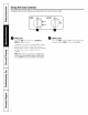
Usingthehoodcontrols. Throughout this manual, features and appearance may vary from your model. OFF HI \ NiTE @___. 0 FAN Control Turn the FAN speed control to LO,MED LO, MED HI or HI, as needed. Continuous use of the tim svstem while cooking helps kee I) the kit(hen comtortable and less hmnid. It also reduces cooking odors and soiling moisture that create a fl'equent need for (leaning. NOTE: When the fan is operating on the tO setting, it will be very quiet.
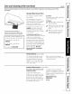
Cam and cleaning of the vent hood. gecom Be sure electrical power is off and all surfaces are cool before cleaning or servicing any part of the vent hood. Reusable Metal Grease Filters The hood grease has The metal released filters trap by fl)ocls on They also fl)ods on the Heavwdutv also commercial lle used in place filte_ of the For 30" hoods, JXBF30SS. order Kit no. For 36" hoods, JXBF36SS. order Kit no. To order, call may filters. this hood should cooktop.
Careand cleaning of the vent hood. Be sure electrical power is off and all surfaces are cool before cleaning or servicing any part of the vent hood. Receptacle Socket % NOTE,"The glass cover should be removed onlywhen cold. Wearing latex gloves may offer a better grip. Glasscover Receptacle CAUTION.
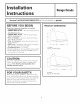
I stall "J I str cti Range Hoods Questions? Call 800.GE.CARES (800.432.2737) or Visit our Website at: BEFORE YOU BEGIN Read these instructions . IMPORT_qTlocal inspector's completely and PRODUCT DIMENSIONS and carefully. S.ve_hesei.s.-,,,._io,,s _o,- use. • IMPORTANT- Observe allgo, codes ge.com erning ordinances. • Note to Installer - Be sure to leaxe these instructions with the (_onsumer. • Note to Consumer - Kee I) these instructions for future reference.
Installation instructions iNSTALLATiON CLEARANCES OPTIONAL These vent hoods are designed to be installed onto a wall. They may be installed beneath a sottit or cabinet. * Install these hoods 24" Min. to 36" Max. above the cooking surt;lce. SOFFIT INSTALLATION SOFFIT F Duct Cover A Decorative ACCESSORIES duct cover is available 8 to 10 _t. ceiling heights. Tile duct cover will expand fi'om 12" Min. or 24"to 34" Max. height.
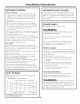
Installation instructions ADVANCE PLANNING DECORATIVE Ductwork Planning " This hood may be vented vertically through upper cabinets, soffit or ceiling. A duct transition piece is supplied for vertical exhaust. Use locally supplied elbows to vent horizontally through the rear wall. See page 13. * Determine the exact location of the vent hood. * Plan the route for venting exhaust to the outdoors. * Use the shortest and straightest duct route possible.
Installation instructions Total DUCT FiTTiNGS Duct Use this chart permissible to compute lengths for maximum duct Frills to Piece Equivalent Quantity Equivalent Dimensions Length* Used Length 7" Round, 1 tl. straight (per t))ot otltdoors. length) 3-1/4" x 12" Note: Do not exceedmaximumpermissibleequivalent l It. straight (per t_)ot lengths! length) Maximum duct length: 100 foot for vent hoods.
Installation instructions TOOLS AND MATERIALS REQUIRED INOTSUPPLIED) REMOVE THE PACKAGING * I,ift out the wooden protective carton. crossmember, *Litt out the four "L" shaped profiles. Pencil and tape measure Phillips and Flat blade screwdrivers Duct tape * I_emove the protection carton box. as well as the top polystyrene moldings around * Remove the small box housing * I,itt the hood ()sit of the box. CAUTION: protection the smaller the motor. b,g,.spi.theo.
Installation instructions PARTS PROVIDED Locate the hardv4_re arcessor} hood and check contents. box packed >Ath tile Screws, wall fasteners, washers Filter Support 2 Aluminum Grease Filters 2 Control Knobs DUCT COVER REQUIREMENTS We recommend that the vent hood and P.eview tile following examples to ensure a trouble installation usino tile duct cover accessory. decorative duct cover (if used) be on site before final Kaming and wall finishing.
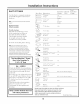
Installation instructions DETERMINE • Measure hood HOOD, DUCTWORK desired distance fl'om to the cooking sm'thce, Refer to the will be used. previous page the 24" if the bottom rain. accessory • lJse centerline hood, top to draw the 18" draw of the duct VENTDUCTING cover up from another the indicating the loc_ltion. the horizontal line another horizontal ior the line. line bottom of the to indicate the horizontal 7-1/2" Dia.Hole, I cooktop 15-3/8" up fl'om of the hood.
Installation instructions [] iNSTALL HOOD SUPPORT iMPORTANT: Framing supporting 100 Ibs. must 12] INSTALL TRANSITION be capable of * Locate at least 2 vertical studs at the wood location by tapping dr)_vall with a hammer stud finder ,b Center the supplied wood horizontal right and below the marked line. IMPORTANT: Remove shipping tape from damper and check that mounting or use a support, damper moves freely.
Installation instructions [4]Alternate Mounting Method iNSTALL HOOD TO SOFFIT OR BENEATH CABINETS IMPORTANT: For additional support and to minimize vibration during operation, we strongly recommend that the hood also be secured to the back wall with wall fasteners. 30"Models SKIP THIS STEP iF USING WALL MOUNTING METHOD 24/16" 1 iMPORTANT: of supporting Soffit framing 100 Ibs. must be capable / ] 7-1/ '1! When necessary, the hood may be installed so that it is supported by the soffit.
Installation instructions iNSTALL CEiLiNG BRACKET CONNECT '_ Push The ceiling bracket must be installed when tile duct cover is used to span 24" or more height above the hood. The bracket will hold the decorative duct cover ill place at the top. Note: The ceiling bracket is not requh'ed only the 12" section of the duct cover. * Install the 2 small screws into the sides when using of the duct duct DUCTWORK over tile end reaches the stop tabs. * Install ductwork, making airflow as illustrated.
Installation instructions [_ iNSTALL MOTOR _] INSTALL * Align and engage slots ill tile blower To install the 12 "duct cover alone: * Place tile 12" section of tile decorative tile top assembly to tile 3 hooks at tile rear of tile exhaust of tile * Secure tile To install * Place motor until upwards it aligns _ith attachl/lellt oo0_0oo o 0 i 0 the o i..... ............
Installation instructions [_ iNSTALL FILTERS * Remove protective * Insert the of the * Tap into vertical the filter opening. * Pull the of the filter filter filter film the "(T' mounted the ti'ont panel. against one down [_ covering into clips INSTALL OPTIONAL COMMERCIAL FILTERS filters. to the top * Remove side the to align lower slots with supplied filters (if installed). outside at the bottom support.
Notes, 9e.
Before you call for service... Troubleshooting -tips Save time and money/. Review the charts on the following pages first and you may not need to call for service. What To Do ii Possible Causes Fandoesnot operate when the switch is on A fuse may be blown or a circuit breaker tripped. • Replace The • Disconnect power to the unit. ]).emove the filters and look up at the blower, If the blower connector plug is loose or van see the connector dangling, the installer tidied to plug it in secm'elv.
GE Service Protection Plus 'M GE, a nante recognized worldwide for quality and dependability; oflers y'ou Service Protection Plus'_'--comprehensive protection on all },'our appliances-No Matter What Brand! Benefits Include: We71CoverAny Appliance. Anywhere. Anytime.
Consumer Dear Product Ownership Registration Customer: Thank you tbr purchasing our product and thank '_'e are proud to haxe you as a customer'. Follow these three steps Complete your to protect you for placing your new appliance mid mail Ownership RegJstra|ion the peace mind of knowing Call COlltaCt the unlikeE store today; Have in us. investment: Read After mailing the registration below, Consumer Product your confidence this doc/llnellt in a sat;_'place.
GERange Hood Warranty. Aft warranty service provided by our Factory Service Centers, or an authorized Customer Care® technician. To schedule service, on-line, 24 hours a day, visit us at ge.com, or carl 800.GE.CARES (800.432.2737). Please have serial number and model number available when calling for service. Staple your receipt here.
ConsumerSupport. a question or need assistance with your "I Haxe GE Appliances Website any da)of the year'. For greater comenience q order parts or e',en schedule service al)pliaure? and Try tile faster ser\'ice, GE Al)pliances you can now _Aebsite 24 hom_ download Owner's a day, ge.com Manuals, on-line. ScheduleService Expert (;E repair sets,ice your, comenience business hom_. ge.