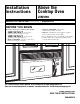
Installation Instructions Above the Cooktop Oven JVM1790 Questions? Call 1-800-361-3400 or Visit our Website at: geappliances.ca BEFORE YOU BEGIN Read these instructions completely and carefully. IMPORTANT – • Save these instructions for local inspector’s use. • IMPORTANT – Observe all governing codes and ordinances. • Note to Installer – Be sure to leave these instructions with the Consumer. Note to Consumer – Keep these instructions for future reference.
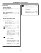
Installation Instructions C CONTENTS Recirculating ........................................ 19–22 Attach Mounting Plate to Wall ............19 General information Preparation of Top Cabinet ................19 Important Safety Instructions .................................. 3 Electrical Requirements .......................................... 3 Adapting Blower for Recirculation ..........................20, 21 Hood Exhaust ...................................................... 4, 5 Mount the Oven ....
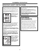
Installation Instructions IMPORTANT SAFETY INSTRUCTIONS This product requires a three-prong grounded outlet. The installer must perform a ground continuity check on the power outlet box before beginning the installation to insure that the outlet box is properly grounded. If not properly grounded, or if the outlet box does not meet electrical requirements noted (under ELECTRICAL REQUIREMENTS), a qualified electrician should be employed to correct any deficiencies.
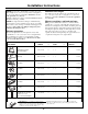
Installation Instructions HOOD EXHAUST NOTE: Read these next two pages only if you plan to vent your exhaust to the outside. If you plan to recirculate the air back into the room, proceed to page 6. OUTSIDE TOP EXHAUST (EXAMPLE ONLY) The following chart describes an example of one possible ductwork installation. EQUIVALENT LENGTH x NUMBER USED = EQUIVALENT LENGTH Roof Cap 24 Ft. (7.3 m) x (1) = 24 Ft. (7.3 m) 12 Ft. (3.6 m) Straight Duct (6”/15.2 cm Round) 12 Ft. (3.6 m) x (1) = 12 Ft. (3.
Installation Instructions Maximum duct length: NOTE: If you need to install ducts, note that the total duct length of 31⁄4” x 10” (8.2 x 25.4 cm) rectangular or 6” (15.2 cm) diameter round duct should not exceed 140 equivalent feet (42.7 m). Outside ventilation requires a HOOD EXHAUST DUCT. Read the following carefully. NOTE: It is important that venting be installed using the most direct route and with as few elbows as possible. This ensures clear venting of exhaust and helps prevent blockages.
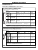
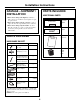
Installation Instructions PARTS INCLUDED DAMAGE—SHIPMENT/ INSTALLATION ADDITIONAL PARTS • If the unit is damaged in shipment, return the PART unit to the store in which it was bought for repair or replacement. • If the unit is damaged by the customer, repair or replacement is the responsibility of the customer. • If the unit is damaged by the installer (if other than the customer), repair or replacement must be made by arrangement between customer and installer. QUANTITY TOP CABINET TEMPLATE 1/4” (0.
Installation Instructions TOOLS YOU WILL NEED Pencil #1 and #2 Phillips screwdriver Tin snips (for cutting damper, if required) Ruler or tape measure and straight edge Scissors (to cut template, if necessary) Electric drill with 3⁄16“, 7⁄16“ ⁄ “ and 5⁄8“ drill bits 12 Carpenter square (optional) Filler blocks or scrap wood pieces, if needed for top cabinet spacing (used on recessed bottom cabinet installations only) Gloves Saw (saber, hole or keyhole) Stud finder or Safety goggles Level Hammer
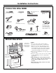
Installation Instructions 1 PLACEMENT OF THE MOUNTING PLATE A. REMOVING THE OVEN FROM THE CARTON/REMOVING THE MOUNTING PLATE B. FINDING THE WALL STUDS 1 Remove the box containing the installation instructions, filters, exhaust adaptor, damper and the small hardware bag. Do not remove the Styrofoam protecting the front of the oven. Wall Studs 2 Fold back all 4 carton flaps fully against carton sides. Then carefully roll the oven and carton over onto the top side.
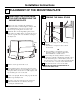
Installation Instructions C. DETERMINING WALL PLATE LOCATION UNDER YOUR CABINET Plate position—beneath framed recessed cabinet bottom Plate position—beneath flat bottom cabinet Mounting Plate Tabs Touching the Cabinet Bottom Mounting Plate Tabs Touching the Back Frame 30″ (76.2 cm) to Cooktop At least 30″ (76.2 cm), up to 36″ (91.4 cm) Plate position—beneath recessed bottom cabinet with front overhang Your cabinets may have decorative trim that interferes with the oven installation.
Installation Instructions D. ALIGNING THE WALL PLATE Hole B Hole A Draw a Vertical Line on Wall from Center of Top Cabinet Hole C CAUTION: Wear gloves to avoid cutting fingers on sharp edges. Hole D Area E 1 Draw a vertical line on the wall at the center of the 30″ (76.2 cm) wide space. 2 Use the mounting plate as the template for the rear wall.
Installation Instructions 2 INSTALLATION TYPES (Choose A, B or C) This oven is designed for adaptation to the following 3 types of ventilation: A. Outside Top Exhaust (Vertical Duct) B. Outside Back Exhaust (Horizontal Duct) C. Recirculating (Non-Vented Ductless) A NOTE: This oven is shipped assembled for Outside Top Exhaust. Select the type of ventilation required for your installation and proceed to that section.
Installation Instructions A OUTSIDE TOP EXHAUST (Vertical Duct) INSTALLATION OVERVIEW A1. Attach Mounting Plate to Wall A2. Prepare Top Cabinet A3. Install Adapter A4. Mount Oven A5. Adjust Exhaust Adaptor A6. Connect Ductwork To use toggle bolts: A1.
Installation Instructions A2. USE TOP CABINET TEMPLATE FOR PREPARATION OF TOP CABINET A4. MOUNT THE OVEN You need to drill holes for the top support screws, a hole large enough for the power cord to fit through, and a cutout large enough for the exhaust adaptor. FOR EASIER INSTALLATION AND PERSONAL SAFETY, WE RECOMMEND THAT TWO PEOPLE INSTALL THIS OVEN. IMPORTANT: Do not grip or use handle during installation.
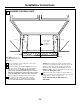
Installation Instructions A4. MOUNT THE OVEN (continued) A5. ADJUST THE EXHAUST ADAPTOR Open the top cabinet and adjust the exhaust adaptor to connect to the house duct. Cabinet Front Cabinet Bottom Shelf Filler Block Damper Equivalent to Depth of Cabinet Recess Back of oven Self-Aligning Screw Oven Top 4 Attach the oven to the top cabinet. 5 Insert 2 self-aligning screws (1⁄4”-28 x 31⁄4”) through outer top cabinet holes. Turn two full turns on each screw. A6.
Installation Instructions B OUTSIDE BACK EXHAUST (Horizontal Duct) INSTALLATION OVERVIEW B1. B2. B3. B4. B5. Prepare Rear Wall Attach Mounting Plate to Wall Prepare Top Cabinet Adjust Blower Mount the Oven B2. ATTACH THE MOUNTING PLATE TO THE WALL B1. PREPARING THE REAR WALL FOR OUTSIDE BACK EXHAUST You need to cut an opening in the rear wall for outside exhaust. Attach the plate to the wall using toggle bolts. At least one wood screw must be used to attach the plate to a wall stud.
Installation Instructions To use toggle bolts: Mounting Plate B4. ADAPTING BLOWER FOR OUTSIDE BACK EXHAUST Spacing for Toggles More Than Wall Thickness Toggle Wings Toggle Bolt Wall 1 Remove the three screws that hold the blower plate to the oven. Slide blower plate from under its retaining flange. Remove and save the screw that holds blower motor to oven.
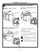
Installation Instructions 5 Roll the blower unit 90° so that fan blade openings are facing out the back of the oven. Before Rolling 8 Replace the blower plate in the same position as before with the screws. Blower Plate Screws Blower Plate After Rolling Back of Oven Back of Oven 9 Insert the tabs on each side of the damper into the holes at the inside rear of the adaptor. Back of Oven 6 Locate the two “knockout” plates, on the rear oven panel, near the top of the oven.
Installation Instructions Cabinet Front B5. MOUNT THE MICROWAVE OVEN Cabinet Bottom Shelf Filler Block Equivalent to Depth of Cabinet Recess Self-Aligning Screw FOR EASIER INSTALLATION AND PERSONAL SAFETY, WE RECOMMEND THAT TWO PEOPLE INSTALL THIS MICROWAVE OVEN. Oven Top 4 Attach the oven to the top cabinet. IMPORTANT: Do not grip or use handle during installation. 5 Insert 2 self-aligning screws (1⁄4”-28 x 31⁄4”) through outer top cabinet holes. Turn two full turns on each screw.
Installation Instructions C RECIRCULATING (Non-Vented Ductless) INSTALLATION OVERVIEW C1. Attach Mounting Plate to Wall C2. Prepare Top Cabinet C3. Adjust Blower C4. Mount the Oven C5. Install Charcoal Filter (not supplied) 3 Place the mounting plate against the wall and insert the toggle wings into the holes in the wall to mount the plate.
Installation Instructions C3. ADAPTING BLOWER FOR RECIRCULATION 3 Carefully pull out the blower unit. The wires will extend far enough to allow you to adjust the blower unit. NOTE: The exhaust adaptor with damper is not needed for recirculating models. You may want to save them for possible future use. 1 Remove and save screws that hold blower plate to the oven. Blower Plate Screws 4 Roll the blower unit 90° so that fan blade openings are facing toward the front of the oven.
Installation Instructions C3. ADAPTING BLOWER FOR RECIRCULATION (continued) NOTE: When mounting the oven, thread power cord through hole in bottom of top cabinet. Keep it tight throughout Steps 1–3. Do not pinch cord or lift oven by pulling cord. 5 Place the blower unit back into the opening. CAUTION: Do not pull or stretch the blower unit wiring. Make sure the wires are not pinched. 6 Secure blower unit to oven with the screw removed in Step 2.
Installation Instructions C6. INSTALLING THE CHARCOAL FILTER C5. MOUNT THE OVEN (continued) 1 Remove 2 screws on top of oven, just above the grille panel, using a Phillips screwdriver. Remove one screw on the left side. 2 Open the door. 3 Remove the grille. 5 Insert 2 self-aligning screws (1⁄4”-28 x 31⁄4”) through outer top cabinet holes. Turn two full turns on each screw. Screws Side Screw 6 Tighten center screw (1⁄4”-28 x 25⁄8”) completely.
Installation Instructions BEFORE YOU USE YOUR MICROWAVE 1. Make sure the oven has been installed according to instructions. 6. ER’S OWN AL U MAN ION LLAT NS A T S IN IO RUCT INST 2. Remove all packing material from the oven. 3. Install turntable and wheeled ring in cavity. 4. Replace house fuse or turn breaker back on. 5. Plug power cord into a dedicated 15 to 20 amp electrical outlet. Read the Owner’s Manual. 7. KEEP INSTALLATION INSTRUCTIONS FOR THE LOCAL INSPECTOR’S USE.
49-40453 (06-05 JR) 24 Printed in Korea