Installation Instructions Overthe Range Microwave Oven Questions?Call 800.GE.CARES(800.432.2737)or Visit,,,, x_ebsite;,t:ge.com BEFORE YOU BEGIN Read these instructions completely • IMPORTANT instructions for local • Note codes and to Installer instructions carefully. - S_,,e these inspector's use. - Obse_,'e _,ll • IMPORTANT governing and ordinances. - Be sure to leave these ° Note to Consumer - KeeI) these instructions for future reterence.
Installation Instructions Redrculating CONTENTS General information hnportant Safety ........................................ Attach Mounting Prepm:ltion Instructions .................................. Hood Requirements Exhaust Damage Mounting Space installation Removing Plate 7 ............................ 8-10 Plato ...................... Aliguiug Wall Plate ............................... Plate l.
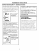
Installation Instructions iMPORTANT SAFETY iNSTRUCTiONS This product requires a three-prong groronled outlet. The installer must perflmu a ground continuit) check on the power outlet box befl_re beginning the installation to insm'e that the outlet box is properly grotmded. If not properly grotmded, or if the outlet box does not meet electrical requirements noted (rolder E1,ECTRICAI_ REQLIIREMENTS), a qualified electrician should be employed to correct any deficiencies.
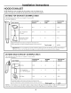
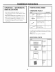
Installation Instructions HOOD EXHAUST NOTE: Read these next two pages only if you plml to vent your exhaust to the outside. If you plan to recirculate the air back into the room, proceed to page 6. OUTSIDE TOP EXHAUST The following chart ductwork instnllation. describes (EXAMPLE an example of one ONLY) possible EQUIVALENT LENGTH DUCT PIECES 12 Ft.Straight Duct RoofCap (6" Round) x 12 Ft. 24 Ft. TransitionAdaptor* Rectangular-to-Round xx 5 Ft. NUMBER USED EQUWALENT LENGTH (1) 24 Ft.
Installation NOTE: If wm duct length round duct Outside the NOTE: x ] O" rectangular should not direct ensm'es blockages. hood that the Maximum total or 6" diameter 140 equivalent a HOOD that route clear and venting make is blocking Exhaust note feet. EXHAUST DUCT. the venting with be installed as few elbows of exhaust and dmnpers swing sure as possible. prevent freely and ducts.
Installation Instructions PARTS iNCLUDED DAMAGE - SHIPMENT/ iNSTALLATiON HARDWARE * If the unit unit is damaged to the store in shipment, in which it was return bought the PART QUANTITY fin" repair Wood Screws or replacement, ® If the unit replacement ® If the th;m unit the PACKET 2 (Y4"x 2") is damaged is the by the customer, responsibility is damaged customer), be made by ;uT;mgement and installer.
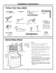
Installation Instructions TOOLS YOU WILL NEED Rulerortape measureand # 1 and#2 Phillipsscrewdriver Pencil tedge (optional) Tin snips(for cutting damper,if required) Scissors (to cut template,if necessary) Electricdrill with ¾_",V/" and%" drill bits Fillerblocksor scrap wood pieces,if needed for top cabinetspacing (usedon recessedbottom cabinet installationsonly) Gloves Saw(saber,hole or keyhole) Studfinder er Safetygoggles MOUNTING Hammer(optional) Ductandmaskingtape Level SPACE NOTES: Bott
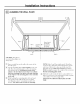
Installation I- PLACEMENT I'_ Instructions OF THE MOUNTING REMOVING THE MICROWAVE OVEN FROM THE CARTON/ REMOVING THE MOUNTING PLATE _ Remove the installation tray and the the Swroioam [] Fold back sides. filters, FINDING THE WALL STUDS glass small hardware bag. Do not remove protecting the fl'ont of the oven. all Then instructions, I-_ 4 carton flaps careflflly onto the top the Stvrofi)am. side.
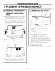
Installation DETERMINING Plate position cabinet Instructions WALL PLATE LOCATION - beneath UNDER YOUR CABINET Plate position - beneath cabinet bottom flat bottom framed Mounting PlateTabs i the CabinetBottom recessed Mounting Plate Tabs Touching the Back Frame -: "*'-,% II 30" to Cooktop At least 30", up to 36" Plate position - beneath recessed cabinet with front overhang bottom Your with cabinets may the microwave trim to install level.
Installation ALIGNING Instructions THE WALL PLATE S ! / "-'-'- Hole B / Ho'e O Oeoter r:f co, Area E CAUTION: to a_oid sharp _4'ear cutting glo_es finget_ on edges. []Draw a vertical 30" wide []Use mortaring wall.
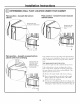
Installation INSTALLATION This the microwave following oven three A. Outside Top B. Outside Back C. Recirculating _A_ is designed types Exhaust TYPES fi)r adaptation Instructions (Choose A, B or C) to NOTE: (Vertical Exhaust (Non-Vented type Duct) (Horizontal This T(>p Exhaust of ventilation: to that is shii)ped for (except of ventilation proceed Duct) microwave required assembled non-vented fl)r models). for yore" Outside Select installation the and section.
Installation Instructions OUTSIDE TOP EXHAUST INSTALLATION A1. A2. A3. A4. (Vertical Duct) OVERVIEW Attach Mounting Plate to Wall Prepare Top Cabinet Check Damper Operation Mount Microwave Oven A5. A(!just Exhaust Adaptor A6. Connect Ductwork i To use toggle ATTACH THE MOUNTING PLATE TO THE WALL bolts: Spacingfor Toggles MoreThanWall +l..-.[.
Installation I-_ You USE TOP CABINET TEMPLATE FOR PREPARATION OF TOP CABINET need hole and Instructions to drill holes enough for large a cutout large fl)r the the power top support cord enom, h_ fi_r the screws, MOUNT OVEN THE MICROWAVE a to fit through, exhaust adaptor. FOR EASIER INSTAI,IATION AND PERSONAl, SAFETY, WE RECOMMEND THAT TWO PEOPLE INSTALL THIS MICROWAVE OVEN. IMPORTANT: % " Read tile instructions on tile TOP CABINET TEMPLATE.
Installation I-_ Instructions MOUNT THE MICROWAVE OVEN (cont.) ADJUST THE EXHAUST ADAPTOR CabinetFront Open 10 CabinetBottomShelf connect the top cabinet and a(!iust 1o tile hotlse duct. the exhaust Filler Block Blower Plate adaptor Backof Microwave Damper to Depth of Cabinet --_Equivalent Recess Self-AligningScrew For Front-to-Backor Side-to-SideAdjustment, Slide the ExhaustAdaptor as Needed MicrowaveOvenTop [4_ Att;_ch the microwave [] oven to the top cabinet.
Installation Instructions OUTSIDE BACK EXHAUST INSTALLATION B1. B2. B3. B4. BS. B6. l-_ (Horizontal OVERVIEW | Prepare Rear Wall Remove Exhaust Adaptor Attach Mounting Plate to _'all Prepare Top Cabinet A(!just Blower Mount the Microwave Oven PREPARING THE REAR WALL FOR OUTSIDE BACK EXHAUST YOtl Ileed to tilt outside exhaust. }lll Duct) Ol)enin_* in the rear REMOVE EXHAUST ADAPTOR This microwave oven is shii)ped assembled for top exhaust.
Installation [-_ ,%,================_ Instructions ATTACH THE MOUNTING PLATE TO THE WALL USE TOP CABINET TEMPLATE FOR PREPARATION OF TOP CABINET i I You need to drill holes for the top support screws and a hole large enouoh for the power cord to fit throu ,h Attach the plate to the wall using toggle bolts. At least one wood screw must be used to attach the plate to a wall stud. []Remove the toggle wings fron/ % the bolts.
Installation Instructions _ ADAPTING MICROWAVE BLOWER FOR OUTSIDE BACK EXHAUST (cont.) []Rotate blower unit counterclockwise BeforeRotation Place the blower unit back into tile () lenin 180 °. After Rotation End CAUTION: Do not pull or stretch the blower tufit wiring. Make sure the wires axe not pinched. NOTE: The blower unit exhaust Microwave _ Microwave e tile wires (;entlv i'eillox from tile Reroute the wires thromd/grooxes of the blower trait.
Installation Instructions CabinetFront MOUNT OVEN THE MICROWAVE CabinetBottomShelf FillerBlock to Depth ofquivalent Cabinet Recess T Self-AligningScrew FOR EASIER INSTALL__TION AND PERSONAL SAFETY, WE RECOMMEND THAT TWO PEOPLE INSTALL THIS MICROWAVE OVEN. MicrowaveOvenTop _ IMPORTANT: Do not grip or use handle during installation. NOTE: If vom" cabinet is metal, use tile nvlon grommet around the power cord hole to prevent cutting of tile cord.
Installation RECIRCULATING INSTALLATION Instructions INo.-Ve.tedDuctlessl OVERVIEW C1. Attach Mounting Plate to Wall C2. Prepare Top Cabinet C3. Check Microwave Assembly C4. A(!just Blower C5. Mount the Microwave C6. Install Charcoal Filter I-_ ()veil []Place the mounting plate against the wall and insert the toggle wings into the holes in the wall to mount the plate.
Installation Instructions CHECK MICROWAVE ASSEMBLY _ Exhaust Adaptor (absent on models shipped for recirculation exhaust Carefully pull out tile blower trait. Tile wires will extend tar enouoh_ to allow _ou to adjust blower trait. tile Backof Microwave ; " Place tile microwave in its upright top of tile unit lacing up. position, with tile * Tile microwave oven may be shipped assembled fin, top exhaust (adaptor installed) or fin" recirculation exhaust (adaptor absent).
Installation | Instructions NOTE: ADAPTING MICROWAVE BLOWER FOR RECIRCULATION []Place the blower the the o motmting oven, thread power cord through hole in bottom of top cabinet. Kee I) it tight (cont.) unit back into When illicrowave I)ening. CAUTION: Do not pull or stretch the blower wiring. Make sure the wires are not pinched. throughout Steps 1-3. Do not pinch cord or lift oxen b) l)ullin,, _ cord.
Installation | Instructions _-_ MOUNT THE MICROWAVE OVEN {cont.) [] [] lnseI't 2 self-aligning sci'ews thi'ough outei" top cabinet holes. Ttli'n two fllll tt/i'ns on each SC I'ew. iNSTALLiNG THE CHARCOAL FILTER On 1400 on fi'ont On 1800 fixmt of tile dooI'. []Open [] and 1600 Series models, remove screws of grille using a #1 Phillips screwdriver. Series models, i'emove screws on top grille using a #2 Phillips screwdriver. Remove the grille. On 1400 and straight off.
Installation Instructions BEFORE YOU USE YOUR MICROWAVE V_ Make sure the microwa'_e o_,en has installed according to inst_ uctions. been -_ Read the Owner's Mantml. N$-_t_LL_\0bl NS-[gUC'[logS A KEEP THE INSTAI,I,ATION INSTRUCTIONS FOR I_OCAL INSPECTOR'S USE. [_] I emoxe illicrowax, Install -_ Replace all )ackino e ox, en. turntable house material and fl/se ring or tm'n from the I in caxitv. breaker back on. I]1 IIIIIIII V_ lug poweroutlet.
49-40538 10-06 ,IR [ Printed in Malaysia