GE Consumer & Industrial Multilin LM10 Motor Protection System Instruction Manual LM10 revision: 1.7x GE publication code: GEK-106642E GE Multilin part number: 1601-0165-A6 Copyright © 2008 GE Multilin GE Multilin Internet: http://www.GEmultilin.
© 2008 GE Multilin Incorporated. All rights reserved. GE Multilin LM10 Motor Protection System instruction manual for revision 1.70. LM10 Motor Protection System, is a registered trademark of GE Multilin Inc. The contents of this manual are the property of GE Multilin Inc. This documentation is furnished on license and may not be reproduced in whole or in part without the permission of GE Multilin. The content of this manual is for informational use only and is subject to change without notice.
1 TABLE OF CONTENTS Table of Contents 1: INTRODUCTION DESCRIPTION .....................................................................................................................1-1 THE LM10 RELAY ............................................................................................................... 1-1 OVERVIEW ...........................................................................................................................1-2 FEATURES ..............................................
TABLE OF CONTENTS 4: FUNCTIONALITY OVERCURRENT FAULT CONDITIONS ............................................................................4-25 DESCRIPTIONS ...................................................................................................................... 4-25 TRIP CURVES EXAMPLE ....................................................................................................... 4-27 CONFIGURATION SETTINGS ............................................................................
1 TABLE OF CONTENTS DEVICENET FEATURES ........................................................................................................ A-3 MAXIMUM CABLE LENGTHS FOR DEVICENET ................................................................. A-3 DEVICENET SPECIFICATION HIGHLIGHTS ......................................................................... A-4 LM10 AND GE FANUC 90-30 WITH DEVICENET™ .....................................................A-6 OVERVIEW .....................................
TABLE OF CONTENTS 1–IV LM10 MOTOR PROTECTION SYSTEM – INSTRUCTION MANUAL
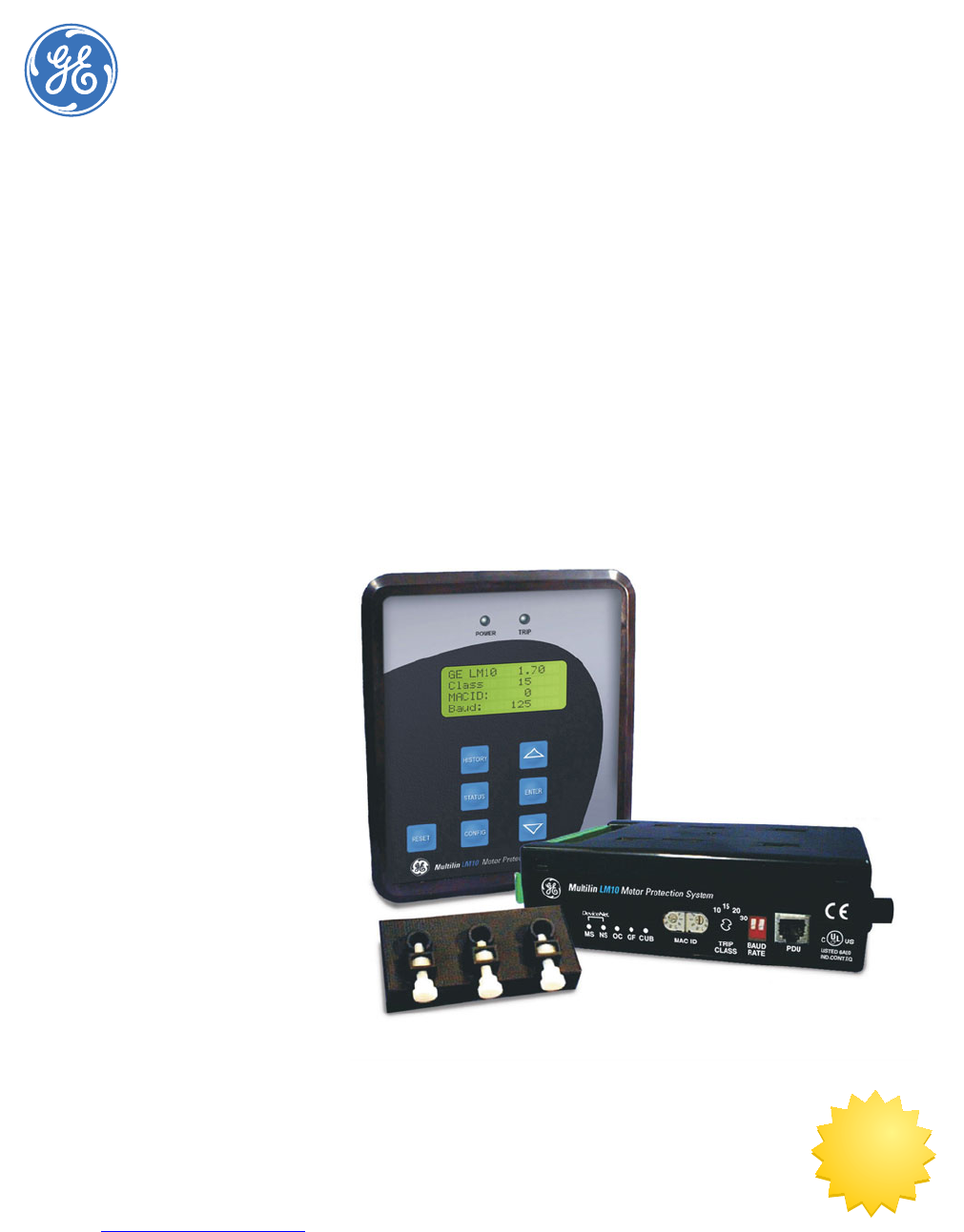
GE Consumer & Industrial Multilin LM10 Motor Protection System Chapter 1: Introduction Introduction 1.1 Description 1.1.1 The LM10 Relay The GE Multilin LM10 Motor Protection System is a modular device designed to protect motors from various fault conditions. This device interfaces with a DeviceNet network. The network will monitor and control the relay status and functions. The relay also has the capability of operating in a standalone mode.
OVERVIEW 1.2 CHAPTER 1: INTRODUCTION Overview 1.2.1 Features The LM10 Motor Protection System is a microprocessor-based unit. It takes a ‘snapshot’ image of the three phases of current, one phase of voltage, and ground. The data is then applied to the algorithms and compared to the device's configuration information. Based on the result of the comparison, the relay may trip one or more of the on-board control relays. When applicable, indicators will be illuminated to show the status of the device.
CHAPTER 1: INTRODUCTION 1.2.4 OVERVIEW Power Supply The LM10 Motor Protection System has an on-board power supply with a fuse that converts the AC input to the levels necessary to operate this device. The operating range is 96 to 140 V AC, nominal 120 V control power (80% to 117%). The supply has programmable auto-restart capability of up to 4 seconds. This also supplies necessary power to the PDU at a TTL.
FEATURES 1.3 CHAPTER 1: INTRODUCTION Features 1.3.1 Programming and Display Unit The main task of the programming and display unit (PDU) is to provide status information to a local user. The PDU can display the requested parameter(s) on the LCD in either English or Spanish. Additionally, the PDU can be used to configure the LM10 via the RS232 serial communications port. 1.3.2 LED Indicators The LM10 has five (5) LEDs on the front panel.
CHAPTER 1: INTRODUCTION FEATURES • Baud rate: This two-position DIP switch is used to select the DeviceNet baud rate. The valid rates are 125K, 250K and 500K bits per second. The DIP switch is defaulted to 125K baud rate when shipped. Baud Rate 125 kbps DIP Switch Position down - down 250 kbps up - down 500 kbps up - up Changes to switch settings will not take effect until the next power cycle. • Trip Class (TC): NEMA overload trip class is selected using a rotary DIP switch.
ORDERING 1.4 CHAPTER 1: INTRODUCTION Ordering 1.4.1 Order Codes The order codes for the LM10 Motor Protection System are shown below.
CHAPTER 1: INTRODUCTION 1.5 SPECIFICATIONS Specifications 1.5.1 Protection Elements OVERCURRENT (ANSI 51) Curve shapes: ..................................................NEMA class 10, 15, 20 and 30, hot and cold Timing accuracy:............................................±5% of total trip time + 1 second GROUND FAULT Pickup level: .....................................................0.4 to 20.0 A in steps of 0.2 Pickup accuracy: ............................................±5% or ±0.
SPECIFICATIONS CHAPTER 1: INTRODUCTION AVERAGE CURRENT Resolution: .........................................................0.1 A Range:..................................................................0.05 to 8 × CT Primary (3200.0 A max.) Accuracy:............................................................±5% of full scale GROUND CURRENT Resolution: .........................................................0.1 A Range:..................................................................0.0 to 25.
CHAPTER 1: INTRODUCTION SPECIFICATIONS Ground CT input:.............................................20 A ground fault sensor or 20:0.2 A ground fault CT VOLTAGE PT secondary:...................................................0 to 120 V PT primary: ........................................................200 to 7200 V CONTACT INPUT Inputs:..................................................................
SPECIFICATIONS 1.5.5 CHAPTER 1: INTRODUCTION CT Dimensions Thermal overload CT Order Code Description Window Diameter Overall Dimensions CT01 Current Sensor, NEMA Starter Size 1, 3 phase, 27 amp 0.44" 4.625"x2.000"x1.375" CT02 Current Sensor, NEMA Starter Size 2&3, 3 phase, 90 amp 0.44" 4.625"x2.000"x1.375" CT03 Current Sensor, NEMA Starter Size 4, 3 phase, 200 amp 0.69" 5.60"x2.38"x1.72" CT04 Current Sensor, NEMA Starter Size 5, 1 phase, 300 amp 1.50" 4.50"x4.88"x4.
CHAPTER 1: INTRODUCTION SPECIFICATIONS Connector type:...............................................5-pin micro-style molded male connector Baud rate: ..........................................................125, 250 and 500 kbps via DIP switches Mac id: .................................................................0 to 63 via DIP switches Supports: ............................................................Poll, COS and Cyclic IO, and explicit messaging LEDs:........................................
SPECIFICATIONS 1–12 CHAPTER 1: INTRODUCTION LM10 MOTOR PROTECTION SYSTEM – INSTRUCTION MANUAL
GE Consumer & Industrial Multilin LM10 Motor Protection System Chapter 2: Installation Installation 2.1 Wiring 2.1.1 DeviceNet The LM10 has one micro-style (Brad Harrison style) connector that allows the purchase of pre-built cables for attachment to the unit and the ability to daisy chain from one unit to the next. These connectors meet all DeviceNet physical layer requirements. FIGURE 2–1: LM10 DeviceNet Pinout 2.1.
WIRING CHAPTER 2: INSTALLATION RJ11 Pin Description 5 +5 V (PDU use only) 6 N/A The LM10 base unit and PDU are designed to use a maximum 36-inch cable when the PDU is mounted door-mounted alone. A shorter cable can be used when the two units are doormounted together. The connection for the RS232 serial communications port is shown in the following figure. The EnerVista LM10 software can be used to configure and monitor the status of the LM10 through the RS232 port. FIGURE 2–2: LM10 RS232 Pinout 2.
CHAPTER 2: INSTALLATION WIRING FIGURE 2–3: LM10 Control Signal Contacts Service hint: Remove the bottom terminal block first, using a small screwdriver in either end. The top terminal block can then be removed using a coin or any broad-blade tool. 2.1.4 Sensor Pack Input Connectors S1 and S2 are used to connect to all CT Sensor Packs. 5 A CTs connect via the Phoenix terminal block. S1/S2 Pins 2.1.
WIRING CHAPTER 2: INSTALLATION FIGURE 2–4: LM10 Wiring Diagram 2–16 LM10 MOTOR PROTECTION SYSTEM – INSTRUCTION MANUAL
CHAPTER 2: INSTALLATION 2.2 MOUNTING Mounting 2.2.1 LM10 Mounting Three mounting options are available. 1. The relay has four holes in the back to allow securing to a mounting plate with screws by others. 2. When mounted in a GE Evolution Series E9000 Motor Control Center, a mounting bracket (provided separately by GE) has been designed to suspend the LM10 base unit inside the MCC bucket. To install, first remove the plastic mounting plate from the LM10. 3.
MOUNTING CHAPTER 2: INSTALLATION FIGURE 2–6: LM10 Backplate Dimensions 2.2.2 PDU Door Mount The PDU can be door-mounted using the gasket and six screws provided. The rear of the unit protrudes through a cutout and is accessible from inside the door. Recommended cutout dimensions and screw hole locations are shown below.
GE Consumer & Industrial Multilin LM10 Motor Protection System Chapter 3: Interface Interface 3.1 PDU Operations 3.1.1 Liquid Crystal Display The liquid crystal display is a 5 × 8 font pixelized character type in a 16-character by 4-line format. A yellow-green background offers good readability under direct sunlight and normal room lighting. The display is reflective, not backlit. Display messages can be changed to Spanish. 3.1.
PDU OPERATIONS CHAPTER 3: INTERFACE power factor, kW, average current, and current unbalance. Pressing the History button again advances to the next history record. • Status: Pressing the Status button displays the current conditions of the LM10. The following items are displayed: phase currents, ground current, voltage, kW, power factor, average current, current unbalance, and elapsed motor hours. • Config.:In User mode (default startup condition, no passcode entered), pressing the Config.
CHAPTER 3: INTERFACE 3.2 PDU SCREENS AND MENUS PDU Screens and Menus 3.2.1 Main Startup Screen The main startup screen displays the following information. These parameters are not programmable via serial communications, but rather are displayed for convenience. See Switches on page 1–4 for setting instructions. 3.2.
PDU SCREENS AND MENUS CHAPTER 3: INTERFACE Run 2 to Run 1 (delay between forward and reverse or between speeds) • Other Settings Sub-menu: The Other Settings menu is used to enable/disable the following: under/overvoltage, maintained vs. momentary switches, auto restart, DeviceNet fault, and 50 vs. 60 Hz system. It is also used to select the data grouping which is read through DeviceNet polling and to reset elapsed time meter. See Chapter 4 for details.
CHAPTER 3: INTERFACE 3.3 ENERVISTA LM10 SOFTWARE EnerVista LM10 Software 3.3.1 Description The EnerVista LM10 software is intended as an interface to the GE Multilin LM10 Motor Protection System. It has all the capabilities of the GE Multilin LM10 Motor Protection System, although some of the operations may differ slightly. The major difference is configuration parameters are not directly changed from the PDU screen, they must be downloaded after modifying.
ENERVISTA LM10 SOFTWARE CHAPTER 3: INTERFACE • Download: Sends the configuration parameters from memory to the connected LM10. Note that you must be logged into the LM10 as a configurator to download configuration parameters. • Upload: Gets the configuration parameters from the connected LM10 and saves them in memory. • Port: Shows the available communications ports. The current selected COM port is indicated by a check mark.
GE Consumer & Industrial Multilin LM10 Motor Protection System Chapter 4: Functionality Functionality 4.1 Overcurrent Fault Conditions 4.1.1 Descriptions When current for any of the three phases becomes greater than the nominal full load current (FLA), the unit calculates time to trip. The FLA, trip class, CT ratio and number of passes/turns through the CT, and current input readings are taken into account. Separate algorithms are used for “cold” and “hot” motors.
OVERCURRENT FAULT CONDITIONS CHAPTER 4: FUNCTIONALITY FIGURE 4–1: Cold Motor Trip Curves FIGURE 4–2: Hot Motor Trip Curves 4–26 LM10 MOTOR PROTECTION SYSTEM – INSTRUCTION MANUAL
CHAPTER 4: FUNCTIONALITY 4.1.2 OVERCURRENT FAULT CONDITIONS Trip Curves Example A trip curves example with jam and stall enabled is shown below. In this example, we have trip class 20, cold motor, with jam at 150% FLA for 120 seconds, and stall at 600% FLA for 12 seconds. FIGURE 4–3: Trip Curve with Jam and Stall Enabled The LM10 will trip on a jam or stall condition if these faults are enabled (see Run 1 and Run 2 Setup on page 4–32). The overcurrent curve cannot be disabled.
OVERCURRENT FAULT CONDITIONS CHAPTER 4: FUNCTIONALITY While the motor is in the cool-down time delay, the PDU status screen will display the fault type followed by a number decrementing from 99. When the number counts down to 0, the message “Ready to Run” will be displayed to indicate the RESET button may be pressed. Once the LM10 is successfully reset, the user may activate the run command.
CHAPTER 4: FUNCTIONALITY 4.2 CONFIGURATION SETTINGS Configuration Settings 4.2.1 Overview An overview of the LM10 programmable parameters is shown below.
CONFIGURATION SETTINGS CHAPTER 4: FUNCTIONALITY Table 4–1: LM10 Programmable Parameters Parameter 4.2.
CHAPTER 4: FUNCTIONALITY CONFIGURATION SETTINGS Configuration Passcode, Login Run Operations Factory default Configuration Run Operations Factory default Configuration Factory deflt 4.2.3 See page –37. See page –38. See page –38. Language PATH: Configuration Ø ENGLISH/SPANISH Configuration ENGLISH CTs & CPTs Starter Type Configuration ENGLISH SPANISH Range: SPANISH, ENGLISH This setting selects the language (either English or Spanish) to display on the PDU interface. 4.2.
CONFIGURATION SETTINGS 4.2.5 CHAPTER 4: FUNCTIONALITY Starter Type PATH: Configuration ØØØ Starter Type Configuration Starter Type RUN 1 Setup RUN 2 Setup Starter Type FVNR .* Range: FVNR, FVR, RV, 2S1W, 2S2W, Custom Select the motor type from the list.
CHAPTER 4: FUNCTIONALITY CONFIGURATION SETTINGS • FLA (full load current) The LM10 Motor Protection System is designed to work in conjunction with a spectrum of motor starters. Therefore it handles full load currents ranging from 1.2 to 800 amps. The correct FLA for the motor in use must be programmed for relay protection to function properly. Enter the full load current (FLA) of the motor.
CONFIGURATION SETTINGS CHAPTER 4: FUNCTIONALITY A 6% voltage unbalance equates to a roughly 25% current unbalance and will frequently cause motor damage. • LdLoss Setup (load loss setup): Load loss is based on watts, defined as follows: watts = 1.732 × average current × voltage × power factor (EQ 4.3) The power factor is determined using the phase relationship between voltage and phase C current readings.
CHAPTER 4: FUNCTIONALITY CONFIGURATION SETTINGS Other Settings Maintained off Range: on, off Other Settings Auto Restart off Range: on, off Other Settings DevNet Fault on Range: on, off Other Settings 50Hz Sys off Range: on, off Other Settings Poll Data 1 Range: 1, 2, 3, 4. Not available for revisions 1.40 and lower Other Settings Reset Run Hrs. Range: on, off One or more optional faults may be enabled after the basic functions are configured.
CONFIGURATION SETTINGS CHAPTER 4: FUNCTIONALITY prior to power loss and not be in run when power is lost, therefore no run state to restart. With the DeviceNet fault enabled, the power recovery would reset the DeviceNet connections and the DeviceNet would act as if it's not communicating thus a DeviceNet fault. Potential safety hazards must be considered and the appropriate setup chosen for each individual application.
CHAPTER 4: FUNCTIONALITY CONFIGURATION SETTINGS * Aux Relay Faults Load Loss off Range: on, off Aux Relay Faults Power Failure off * Range: on, off Aux Relay Faults Aux Sense off Range: on, off Aux Relay Faults Device Net off Range: on, off Aux Relay Faults Volt Range off Range: on, off Feature currently not available. An auxiliary relay can be connected to any number of warning devices.
CONFIGURATION SETTINGS CHAPTER 4: FUNCTIONALITY Entering a passcode at the Pass Code, Login screen will change the login indicated by an asterisk at the end of the line. The default passcode is “0”. You must be logged in as “Config” to be able to change the passcode. The green power LED will flash while logged in as configurator. The unit will stop any run relay when in configuration mode. The LM10 must be returned to user mode before beginning normal operations.
CHAPTER 4: FUNCTIONALITY 4.3 STATUS VALUES Status Values 4.3.1 Main Menu The main menu for the status values is shown below. Press the STATUS key to access these values. GE LM10 1.70 Class: 10 MAC ID: 1 Baud: 500 LM10 MOTOR PROTECTION SYSTEM – INSTRUCTION MANUAL Status Active Ready to Run Range: Running 1, Running 2, Ready to Run, Fault Status Active Phase A: 0.0 Range: 0.0 to 3200.0 A Status Active Phase B: 0.0 Range: 0.0 to 3200.0 A Status Active Phase C: 0.0 Range: 0.0 to 3200.
STATUS VALUES CHAPTER 4: FUNCTIONALITY • Motor Hrs: The LM10 keeps a running tally of motor operation time, incremented hourly up to 65535 hours. Upon power loss, the unit will retain any whole number of hours already recorded. This feature is a great service tool. An example is for bearing change; the typical maximum bearing life is 50000 hours. This value can be reset via the Reset Run Hrs configuration setting.
CHAPTER 4: FUNCTIONALITY 4.4 HISTORY VALUES History Values 4.4.1 Last Trip Data Data for the last ten trips is stored in the LM10. Press the HISTORY key to access these values. Pressing the HISTORY key multiple times scrolls between trips 1 to 10. GE LM10 1.70 Class: 10 MAC ID: 1 Baud: 500 LM10 MOTOR PROTECTION SYSTEM – INSTRUCTION MANUAL Last Trip #1 Overcurrent Range: Overcurrent, Gr. Fault, Jam, Stall, CuUnbalance, LdLoss, DevNet Fault, Dev Stop, Voltage, Aux Sense Last Trip #1 Phase A: 0.
MOTOR START/STOP LOGIC 4.5 CHAPTER 4: FUNCTIONALITY Motor Start/Stop Logic LM10 is designed to run in RUN1 and RUN2 mode. However, to illustrate this, only RUN1 mode is described below. The block logic diagram for RUN1 operation is shown in fig. 4-5. Motor Status: Running 1 The relay can receive the RUN1 Start command as follows: 1. Start command through hardware RUN1 switch input 2. The RUN1 command is selected from the PDU in the configuration mode (used for Test only) 3.
CHAPTER 4: FUNCTIONALITY MOTOR START/STOP LOGIC AUX. Sense 1 fault detects a welded contactor when the contactor fails to open within 0.4 seconds after the RUN1 O/P signal goes off.
MOTOR START/STOP LOGIC 4–44 CHAPTER 4: FUNCTIONALITY LM10 MOTOR PROTECTION SYSTEM – INSTRUCTION MANUAL
GE Consumer & Industrial Multilin LM10 Motor Protection System Chapter 5: Communications Communications 5.1 DeviceNet Operations 5.1.1 Description The device profile is an extension of the Motor Starter Device Profile (0x16). It is a group 2 only server. It has two (2) LEDs (NET status, Module status), and hardware selectable only MAC ID and baud rate DIP switches.
DEVICENET OPERATIONS CHAPTER 5: COMMUNICATIONS . Table 5–1: Poll Data Group 1 Bytes 7 bytes Data Length 1 byte Name/Description Motor status Data Format Value F21 --- 1 word Phase A current UINT × 0.1 A 1 word Phase B current UINT × 0.1 A 1 word Phase C current UINT × 0.1 A This data group can also be retrieved via explicit messaging to the Assembly object, class 4, instance 102, attribute 3.
CHAPTER 5: COMMUNICATIONS DEVICENET OPERATIONS The Hi and Lo bytes of the phase current A, B and C are reversed as compared to poll group 1 to make it compatible with the format of Firmware revision 1.40 polling data. This data group also can be retrieved via explicit messaging to the assembly object class 4, instance 105, attribute 3. UINT = 16 bit unsigned integer. See Data Formats on page 5–57 for details on the F20, F21, and F22 data formats. 5.1.
DEVICENET OPERATIONS CHAPTER 5: COMMUNICATIONS DeviceNet Object, Class Code 3, Instance 1, Attributes: Attribute 5.1.6 Access Name/Description Data Type Value 2 Get Baud Rate, value 0 to 2 (125, 250, and 500 kbps) UINT from DIP switches 5 Get Allocation information STRUCT from service Assembly Object The assembly objects bind attributes of multiple objects to allow data to or from each object to be sent or received over a single connection.
CHAPTER 5: COMMUNICATIONS DEVICENET OPERATIONS Data Formats for Extended Device Outputs Bit Position Name Value Bit 3 Reserved --- Bit 2 Reserved --- Bit 1 Run 2 --- Bit 0 Run 1 --- Assembly Object, Class Code 4, Instance 5: Attribute 3 Access Set Name/Description Extended device outputs (see format and mapping below) Data Type byte Value see below Data Formats for Extended Device Outputs Bit Position Name Value Bit 7 Reserved --- Bit 6 Reserved --- Bit 5 Reserved --- Bit 4
DEVICENET OPERATIONS CHAPTER 5: COMMUNICATIONS Data Formats for Device Inputs Bit Position Name Value Bit 4 Reserved --- Bit 3 Reserved --- Bit 2 Running 1 --- Bit 1 Warning --- Bit 0 Fault --- Assembly Object, Class Code 4, Instance 54. Use this object for data received by the master from the slave device.
CHAPTER 5: COMMUNICATIONS DEVICENET OPERATIONS Data Formats for Device Inputs Bit Position Name Value Bit 7 DeviceNet Stop Issued Last --- Bit 6 Reserved --- Bit 5 DeviceNet Control --- Bit 4 Reserved --- Bit 3 Running 2 --- Bit 2 Running 1 --- Bit 1 Reserved --- Bit 0 Fault --- Assembly Object, Class Code 4, Instance 102 Attribute 3 Access Get Name/Description Data Type Poll Data Group 1 see below Value see below Data Formats for Device Inputs Bytes 7 bytes Data Length
DEVICENET OPERATIONS CHAPTER 5: COMMUNICATIONS Data formats for device inputs Bytes Data Length 22 bytes Name/Description Data Format Value 1 word Motor status F22 --- 1 word Cause of trip F20 --- 1 word Phase A current UINT × 0.1 A × 0.1 A 1 word Phase B current UINT 1 word Phase C current UINT × 0.1 A 1 word Ground current UINT × 0.1 A 1 word Voltage UINT volts 1 word Power factor UINT × 0.01 1 word Power UINT × 0.1 kW 1 word Average current UINT × 0.
CHAPTER 5: COMMUNICATIONS DEVICENET OPERATIONS Attribute Access Name/Description Data Type Value 4 Get Produced connection ID UINT MAC ID 5 Get Consumed connection ID UINT MAC ID 6 Get Initial comm.
DEVICENET OPERATIONS CHAPTER 5: COMMUNICATIONS Attribute 5.1.
CHAPTER 5: COMMUNICATIONS DEVICENET OPERATIONS Overload Object, Class Code 0x2C, Instance 1: Attribute Access Name/Description Data Type Value 3 Get FLA INT --- 4 Get Trip Class USINT --- 5 Get Average Current INT --- 6 Get Phase Unbalance USINT --- 8 Get Current Phase A INT --- 9 Get Current Phase B INT --- 10 Get Current Phase C INT --- 11 Get Ground Current INT --- 12 Get Current Scale (fixed at 100 mA) SINT 1 UINT = 16-bit unsigned integer 5.1.
DEVICENET OPERATIONS CHAPTER 5: COMMUNICATIONS Attribute Access Name/Description Data Type Value 0x09 Get/set User setting, Run 2, stall F4 Trip, Time 0x0A Get/set User setting, Run 1, unbalance F5 Trip, Time 0x0B Get/set User setting, Run 2, unbalance F5 Trip, Time 0x0C Get/set User setting, Run 1, load loss F6 Trip, Time 0x0D Get/set User setting, Run 2, load loss F6 Trip, Time 0x0E Get/set User setting, power transformers F7 0 to 11 0x0F Get/set User setting, curren
CHAPTER 5: COMMUNICATIONS DEVICENET OPERATIONS 5.1.11 Data Formats F1: Full Load Current (16-bit unsigned integer) Range: 0x000C to 0x1F40 (i.e. 1.2 to 800.0 A) Multiplying factor: 0.1 Example: 123.4 stored as 1234 F2: Ground Fault Format: two bytes in format 0xHHLL, where LL is the pickup level and HH is the time delay Byte LL range: 0x00, 0x02 to 0x64 (i.e. 0.4 to 20.0 A), where 0x00 is disabled Byte LL multiplying factor: 0.2 (i.e. actual = byte LL in decimal × 0.2 amps) Byte HH range: 0x00 to 0x19 (i.
DEVICENET OPERATIONS CHAPTER 5: COMMUNICATIONS Value CT Ratio Value CT Ratio 2 90 A sensor pack 10 300:5 3 75:5 11 400:5 4 100:5 12 500:5 5 120:5 13 600:5 6 150:5 14 700:5 7 200:5 15 800:5 8 225:5 F9: Auxiliary Sense 1 / Run1-Run2 Time Delays Format: two bytes in format 0xHHLL, where LL is the auxiliary sense 1 time delay and HH is the Run1-Run2 time delay (Run1-Run2 time delay for revisions 1.40 and lower only) Byte LL range: 0x00 to 0xFA (i.e. 0.0 to 25.
CHAPTER 5: COMMUNICATIONS DEVICENET OPERATIONS Byte LL range: 0x01 to 0x04 (i.e.
DEVICENET OPERATIONS CHAPTER 5: COMMUNICATIONS Bitmask Cause of Trip ---- -1-- ---- ---- DeviceNet fault ---- 1--- ---- ---- Reserved ---1 ---- ---- ---- Under/overvoltage F21: Motor Status (8-bit Bitmask) Bitmask ---- ---1 Status Fault ---- --1- Reserved ---- -1-- Running 1 ---- 1--- Running 2 ---1 ---- Reserved --1- ---- Control from DeviceNet -1-- ---- Aux Sense 1 input status 1--- ---- Aux Sense 2 input status F22: Motor Status (16-bit bitmask) Bitmask Other Settings ---- ---
CHAPTER 5: COMMUNICATIONS DEVICENET OPERATIONS Bitmask Status 1--- ---- ---- ---- Motor hot at time of fault The third 4-bit section is an enumeration which indicates the cause of the fault.
DEVICENET OPERATIONS CHAPTER 5: COMMUNICATIONS This data was initially setup for development purposes. An explicit message through the custom class 100(0x64) is the only way to access this data. The DeviceNet message to read this data is: service 0x0e, class 0x64, instance 1, and attribute 0x34. The response will be a 16-bit word with MACID switches in the high byte and AC switch input bits in the low byte.
CHAPTER 5: COMMUNICATIONS 5.2 SERIAL PORT Serial Port 5.2.1 Description This is a standard RS232 port to handle the serial messages. It has a fixed port settings of 19200, 8, N, 1. The PDU uses this port. The protocol for request and response of data is a fixed 8-byte packet. It will always start with SOH and end with a simple checksum (~sum + 1). The packets will include all the functionality found in the DeviceNet Extension object. The data is in ‘big endian’ format here (big end first: MSB-LSB).
SERIAL PORT 5–64 CHAPTER 5: COMMUNICATIONS LM10 MOTOR PROTECTION SYSTEM – INSTRUCTION MANUAL
GE Consumer & Industrial Multilin LM10 Motor Protection System Chapter 6: Miscellaneous Miscellaneous 6.1 Revision History 6.1.1 Release Dates Table 6–1: Release Dates Manual 6.1.2 GE Part Number LM10 Revision Release Date GEK-106642 1601-0165-A1 1.37 25 October 2004 GEK-106642A 1601-0165-A2 1.40 17 December 2004 GEK-106642B 1601-0165-A3 1.50 22 February 2006 GEK-106642C 1601-0165-A4 1.60 19 January 2007 GEK-106642D 1601-0165-A5 1.
REVISION HISTORY CHAPTER 6: MISCELLANEOUS Table 6–3: Changes to Manual Since Release A4 Section Number Revision 3.2.4 Move section to 5.1.10 5.1.2 Add Poll Data 4 5.1.6 Add Assembly Object, Class Code 4, Instance 105 (Poll Data Group 4) 5.1.8 Control Supervisor Object - Delete Section 5.1.11 Change format code F15 to include Poll Data Group 4 5.1.
CHAPTER 6: MISCELLANEOUS 6.2 WARRANTY Warranty 6.2.1 GE Multilin Warranty General Electric Multilin (GE Multilin) warrants each device it manufactures to be free from defects in material and workmanship under normal use and service for a period of 24 months from date of shipment from factory.
WARRANTY 6–68 CHAPTER 6: MISCELLANEOUS LM10 MOTOR PROTECTION SYSTEM – INSTRUCTION MANUAL
GE Consumer & Industrial Multilin LM10 Motor Protection System Appendix A A.1 DeviceNet Overview A.1.1 Description DeviceNet™ is an open low-cost digital, multi-drop network based on the reliable CAN technology to interconnect industrial devices (such as limit switches, photoelectric sensors, valve manifolds, motor starter, process sensors, panel displays, etc.) via a single network. This eliminates expensive wiring and failure due to the increase of number of connections.
DEVICENET OVERVIEW A.1.2 CHAPTER A: Controller Area Network (CAN) The Controller Area Network (CAN) is a broadcast-oriented communications protocol. DeviceNet uses CAN for its data link layer. The CAN protocol has a fast response and high reliability for demanding applications such as control of anti-lock brakes and air-bags. Devices are now available for the industrial automation market demanding stability in high temperature and high noise immunity. A.1.
CHAPTER A: A.1.4 DEVICENET OVERVIEW Explicit Messaging and Input/Output (I/O) Messaging Explicit messages contain information such as vendors, parameters, etc. of a device. This information is comparatively less important than the I/O message; as such, it is sent with a higher CAN identifier as not to disturb the exchange of I/O messages on the bus. Input/Output (I/O) messages contain the real-time I/O information of a device.
DEVICENET OVERVIEW CHAPTER A: Table A–1: Trunk Cable Length Specification Baud rate 100% thick cable 100% thin cable Flat cable 125 kbps 500 meters 100 meters 420 meters 250 kbps 250 meters 100 meters 200 meters 500 kbps 100 meters 100 meters 100 meters Table A–2: Drop Cable Length Specification Baud rate A.1.
CHAPTER A: DEVICENET OVERVIEW The Object Model: The Object Model provides a template for organizing and implementing the Attributes, Services and Behaviors of the components of a DeviceNet product. The model provides an addressing scheme for each Attribute consisting of four components i.e Node Address, Object Class Identifier, Instance Number, and Attribute Number.
LM10 AND GE FANUC 90-30 WITH DEVICENET™ A.2 CHAPTER A: LM10 and GE Fanuc 90-30 with DeviceNet™ A.2.1 Overview This section describes an example communications setup between the LM10 Motor Protection System and the GE Fanuc 90-30 PLC via the DeviceNet protocol. • Explicit Messaging: for configuration and monitoring. • All the values mentioned in DeviceNet™ object model (voltage, current, power factor, trip class, FLA settings, etc.) can be monitored.
CHAPTER A: LM10 AND GE FANUC 90-30 WITH DEVICENET™ Z Select GE LM10 under GE Multilin. If the slave is not displayed in the slave catalog, it can be added using the EDS file: Z Click the Have Disk tab in the slave catalog, then open the EDS file for the LM10. We can also add the slave device to the master card from Tool Chest: Z Click the Tool Chest icon in the tool bar.
LM10 AND GE FANUC 90-30 WITH DEVICENET™ CHAPTER A: Z Enter a value of 7 bytes under input resource and 1 byte under output resource. This is the size of the slave status data and command data. Z Make changes to the slave side settings. Z Under the General tab, set the MAC ID equal to the MAC ID of the slave device. Z Select the Polled option under the Connection 1 tab. The input and output byte size are defined and connection type is Status and Control.
CHAPTER A: LM10 AND GE FANUC 90-30 WITH DEVICENET™ Phase A values are displayed in %I00105 (223 × 0.1 amps). Phase B values are displayed in %I00121 (212 × 0.1 amps). Phase C values are displayed in %I00137 (218 × 0.1 amps). The Control Byte via Polled I/O is displayed in %Q00017. The Status Byte via COS is displayed in %I00145. The value displayed in register %R0256 is the voltage parameter received by the master from the LM10 via Explicit Messaging. 9.
LM10 AND GE FANUC 90-30 WITH DEVICENET™ A.2.6 CHAPTER A: COS (Change of State) Input/Output Connection With change of state, a device will produce data only when it changes state. The Change of State Input/Output (COS I/O) connection is primarily used for alarm and status notification. In the LM10, COS data is described in Object Class 4, instance 54. Use the following procedure to establish the COS I/O connection between the LM10 and PLC.
CHAPTER A: LM10 AND GE FANUC 90-30 WITH DEVICENET™ Z Double-click the added slave device to view the data area for Connection 2. Z Open the Reference View Table and add address %I00089. Z To interpret the 1 byte of status information for address %I00097, refer to Object Class 4, Instance 54 in Assembly Object on page 5– 48. A.2.8 Explicit Messaging Description: Explicit messaging provides multi-purpose, point-to-point communication paths between two devices.
LM10 AND GE FANUC 90-30 WITH DEVICENET™ CHAPTER A: • Rung 3 has a Block Move word, 3 blocks. • Rung 4 has the COMMREQ ladder instruction. Refer to Chapter 5: Communications for a complete description of each word. In the ladder below, the Trip Class is read from the slave (LM10 device) MAC ID 1.
CHAPTER A: LM10 AND GE FANUC 90-30 WITH DEVICENET™ FIGURE A–1: Ladder Logic for Data Monitoring Login (Configuration Level) to the LM10: The ladder logic for configuring (login, user level, and entry configuration mode) the LM10 using COMMREQ is shown below. The ladder logic is configured as follows: • Rung 1 and 2 have a timer (thousands), as well as set and Reset coils, which toggles the T1 contact after the value in timer PV overflows.
LM10 AND GE FANUC 90-30 WITH DEVICENET™ CHAPTER A: • Word 13: Login, User Level (for example, 16#33 [Login, User Level]) • Word 14: Object Class to which the Request is directed (for example, 16#64) • Word 15: Instance of Object Class (for example, 1) • Word 17: Attribute (for example, 16#5100 [Configuration]) • Word 18: Passcode, value: 1 FIGURE A–2: Ladder Logic for Login (Configuration) Making Setting Changes: The ladder logic for making setting changes in the LM10 using COMMREQ is shown below.
CHAPTER A: LM10 AND GE FANUC 90-30 WITH DEVICENET™ • Word 17: Attribute (for example, 16#0200 [FLA Run1]) • Word 18: Attribute (for example, 77 [77 × 0.1 amps]) FIGURE A–3: Ladder Logic for Setting Changes Login (User Level) to the LM10: The ladder logic for login (user level) to the LM10 using COMMREQ is shown below.
LM10 AND GE FANUC 90-30 WITH DEVICENET™ CHAPTER A: To view the slave number of slaves connected to master card, add address %I00001 to the new reference table. Now, address %I000010 will read “1”, since the LM10 is connected to the master as slave 1 (MAC ID 1).
CHAPTER A: A.3 LM10 AND ALLEN-BRADLEY SLC500 VIA DEVICENET™ LM10 and Allen-Bradley SLC500 via DeviceNet™ A.3.1 Description This section describes DeviceNet communications between the Allen-Bradley SLC500 PLC card with the GE Multilin LM10 Motor Protection System. The application example shows how to establish communications between Allen-Bradley SLC500 PLC (1747-SDN DeviceNet Scanner) card with the LM10 via Polled I/O Messaging, COS I/O Messaging, and Explicit Messaging. A.3.
LM10 AND ALLEN-BRADLEY SLC500 VIA DEVICENET™ CHAPTER A: Z Once the DeviceNet connection (consisting of the 1747-SDN Scanner card, 1770-KFD, and LM10 relay) is complete, click the Online icon and upload the network. Scanning for the Nodes on the Network will start. Using the EDS Wizard, add the LM10 to the hardware list in RSNetworx. A sample screen of RSNetworx with 3 nodes is shown below.
CHAPTER A: LM10 AND ALLEN-BRADLEY SLC500 VIA DEVICENET™ FIGURE A–6: Sample Force File Z To place the 1747-SDN scanner in Run Mode, toggle the bit O:1/0 to 1 in the O0-output force file. The CPU will change to the Run state. When the scanner is in Run mode and the network is healthy, the node number of the scanner is displayed on the 7-segment indicator on the module. In this case, “63” will be displayed. Z Toggle the O:1/0 to 0 in the O0-output force file to place/force the Scanner to Idle mode.
LM10 AND ALLEN-BRADLEY SLC500 VIA DEVICENET™ CHAPTER A: FIGURE A–7: Scanner Module Scanlist Z Click on Scanlist tab. The LM10 will be shown under Available Devices. Z Click the right arrow to move under 'scanlist'. Double-click on LM10-1 icon to edit the input/output parameters. Z Select Polled and add 1 byte for the Input Size and Output Size. After adding the input/output parameters, you will be prompted for downloading to node 9 A.3.
CHAPTER A: LM10 AND ALLEN-BRADLEY SLC500 VIA DEVICENET™ Z In RSLogix 500, open the O0-Output and I1-Input force files. FIGURE A–8: Input Force File Z To turn on the Run1 contactor, toggle the O:1/16 bit to 1. To turn off Run1, set this bit to 0. The status of the Run1 contactor is indicated by the I:1.1/18 bit. The remote (DeviceNet) control is indicated by the I:1.1/21 bit. The COS I/O messaging data is available in the I1-Input file, bits I:1.1/24 and onwards. A.3.
LM10 AND ALLEN-BRADLEY SLC500 VIA DEVICENET™ CHAPTER A: Table A–3: Status Codes Provided by ODVA Specification Status Data A.3.
CHAPTER A: LM10 AND ALLEN-BRADLEY SLC500 VIA DEVICENET™ • 0E (hex), 14 (decimal) = Get Attribute Single (read a single parameter) • 10 (hex), 16 (decimal) = Set Attribute Single (write a single parameter) • 32 (hex), 50 (decimal) = Get Attribute Multiple (read multiple parameters) The MAC ID low byte is destination code 09. The transaction body consists of the Class, Instance, Attribute, and Data bytes. A.3.10 Ladder Logic This discussion refers to the Ladder Logic diagrams shown on the following pages.
LM10 AND ALLEN-BRADLEY SLC500 VIA DEVICENET™ CHAPTER A: Table A–7: Data to Get Motor Run Time Address Data (hex) Description N19:0 0101 TXID / Command N19:1 0008 Port / Size N19:2 0E09 Service / MAC ID (destination = 63) N19:3 0064 Class N19:4 0001 Instance N19:5 0015 Attribute (Motor Run Time) Table A–8: Data for Explicit Message Response, M1 Transferred to N20 Address Data (hex) Description N20:0 0101 TXID / Command N20:1 0002 Port / Size N20:2 8E09 Service / MAC ID (Node
CHAPTER A: LM10 AND ALLEN-BRADLEY SLC500 VIA DEVICENET™ FIGURE A–9: Ladder Logic, Rungs 0000 to 0005 LM10 MOTOR PROTECTION SYSTEM – INSTRUCTION MANUAL A–25
LM10 AND ALLEN-BRADLEY SLC500 VIA DEVICENET™ CHAPTER A: FIGURE A–10: Ladder Logic, Rungs 0006 to 0008 A–26 LM10 MOTOR PROTECTION SYSTEM – INSTRUCTION MANUAL
CHAPTER A: LM10 AND ALLEN-BRADLEY SLC500 VIA DEVICENET™ FIGURE A–11: Ladder Logic, Rungs 0009 to 0013 LM10 MOTOR PROTECTION SYSTEM – INSTRUCTION MANUAL A–27
LM10 AND ALLEN-BRADLEY SLC500 VIA DEVICENET™ A–28 CHAPTER A: LM10 MOTOR PROTECTION SYSTEM – INSTRUCTION MANUAL
INDEX Index Index A APPLICATION ..................................................................................................... 5-61 AUTORESTART .................................................................................................. 4-35 AUXILIARY RELAY .............................................................................................. 4-37 AUXILIARY SENSE FAILURE ............................................................................... 4-34 B BAUD RATE .................
INDEX G GF INDICATOR ..................................................................................................... 1-4 GROUND FAULT .......................................................................................... 1-4, 4-33 GROUND FAULT RELAY ....................................................................................... 1-2 H HISTORY VALUES .............................................................................................. 4-41 HUMIDITY ................................
INDEX OVERVOLTAGE .................................................................................................. 4-35 P PASSCODE ......................................................................................................... 4-37 PDU ..................................................................................................................... 1-4 POLL GROUP ...................................................................................................... 4-36 POWER SUPPLY ........
INDEX I–4 LM10 MOTOR PROTECTION SYSTEM – INSTRUCTION MANUAL