
Installation and Maintenance Manual


GEI-M1031-B
8
III. INSTALLATION (cont’d)
C. Alignment (cont’d)
1. Direct Coupling (cont’d)
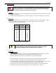
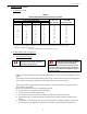
Table 2: Bolt Grade Designations Table 3: Mounting Bolt Torques
For hardware that is less than SAE Grade 5, use 50% of the above recommended
tightening torques. There are no ID marks on bolts that are less than SAE Grade 5.
2. End-Play Adjustment
The axial position of the motor frame with respect to the load is important. The
bearings furnished with these motors are not designed to take any external axial thrust
load unless specifically requested by the purchaser.
3. Belt Drive
The application of pulleys, sheaves, sprockets and gears on motor shafts are shown in
NEMA MG1-14.07. For more information on allowable sheave sizes, refer to the AC
Motor Selection and Application Guide, GET-6812.
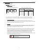
Align the sheaves carefully to avoid axial thrust on the bearings. Belt tension should
just prevent slippage when the motor is running at full load. Excessive belt tension
causes unnecessary load on the bearings. This may be especially true on high-inertia
loads where belts may be tightened to prevent squealing and slipping during
acceleration. On drives of this type, the belts should be allowed to slip during
acceleration to prevent the possibility of overloading the motor bearings. Refer to Table
4 for V-Belt sheave diameter information.
Bolt Size
Recommended Torque
in Ft-Lb (N-M)
Inch
(Metric)
Minimum
Maximum
1/4
(M6)
7
(9)
11
(15)
5/16
(M8)
14
(19)
21
(28)
3/8
(M10)
25
(34)
37
(50)
½
(M12)
60
(81)
90
(122)
5/8
(M16)
120
(163)
180
(244)
3/4
(M20)
210
(285)
320
(433)
Warning
The belt speed should not exceed 6,000 feet per minute
unless otherwise recommended by the manufacturer of
the belt and sheave.
8.8
88
Grade 5
ISO 8.8
OR