
Installation and Maintenance Manual


GEI-M1031-B
9
III. INSTALLATION (cont’d)
C. Alignment (cont’d)
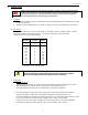
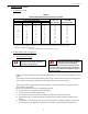
Table 4
V-Belt Sheave Diameters (Minimum in Inches)
Horsepower
Conventional*
Narrow
Synchronous Speed (RPM)
A, B, C, D, E
3V, 5V, 8V
3600
1800
1200
900
Pitch Diameter
Outside Diameter
1.5
1
.75
.50
2.2
2.2
2 – 3
1.5 – 2
1
.75
2.4
2.4
—
3
1.5
1
2.4
2.4
—
—
2
1.5
2.4
2.4
5
—
—
—
2.6
2.4
7.5 – 10.0
5 – 7.5
3 – 5
2 – 3
3.0
3.0
—
10
7.5
5
3.8
3.8
15
15
10
7.5
4.4
4.4
20 – 25
20
15
10
4.6
4.4
—
25
—
5.0
4.4
—
30
20
15
5.4
5.2
—
40
25
20
6.0
6.0
—
50
30 - 40
25 - 30
6.8
6.8
* Maximum sheave width = 2(N-W) – ¼” where N-W is the approximate usable shaft length.
Maximum sheave width = N-W.
(Reference table taken from NEMA MG1-Part 14.)
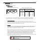
D. Power Supply and Connections
1. Wiring and Grounding
Stator winding connections should be made as shown on the connection diagram on the
motor.
The motor frame should be grounded by attaching a ground strap from a known ground
point to the bronze-grounding bolt in the conduit box or on motor frame.
Terminal board kits are available upon request. If a terminal board is required see KS
TEFC Value Line catalog.
Before the conduit box cover is closed be sure that:
a. All terminal box connections are fixed tightly.
b. The minimum air distances are met.
c. The interior of the terminal box is clean and free from foreign materials.
d. Cable openings not used should be closed and the closing screws should be fixed
tightly.
e. The gasket in the terminal box cover should be clean and tightly sealed to the cover.
f. The condition of all gaskets should be in accordance with protective regulations.
Warning
Where unexpected starting can be
dangerous to personnel, do not use
automatic reset protection.
Warning
Motor and control wiring, overload
protection, and grounding should be
in accordance with the National
Electrical Code and consistent with sound local
practices. Failure to observe these precautions
may result in damage to the equipment, injury to
personnel, or both.