Installation Instructions Built-In Dishwasher If you have questions, call 800-GECARES or visit our website at: www.GEAppliances.com READ CAREFULLY. KEEP THESE INSTRUCTIONS.
Installation Preparation PARTS SUPPLIED: Two #8 Phillips flat head wood screws, 5/8" long to secure dishwasher to underside of countertop or sides of cabinetry. (Taped to top or side of dishwasher.) Side and top trim pieces Trim Panel Accessory Kit (not shown).
Installation Preparation PREPARE DISHWASHER ENCLOSURE • The dishwasher must be installed so that drain hose is no more than 10 feet in length for proper drainage. 34-1/2"±1/4" Underside of Countertop to Floor This Wall Area must be Free of Pipes or wires 5" 4" WARNING 6" 24" Min. Figure A To reduce the risk of electric shock, fire, or injury to persons, the installer must ensure that the dishwasher is completely enclosed at the time of installation. 24" 5" 4" Min.
Installation Preparation PREPARE ELECTRICAL WIRING Alternate Receptacle Location WARNING FOR PERSONAL SAFETY: Remove house fuse or open circuit breaker before beginning installation. Do not use an extension cord or adapter plug with this appliance. Electrical Requirements • This appliance must be supplied with 120V, 60 Hz., and connected to an individual properly grounded branch circuit, protected by a 15 or 20 ampere circuit breaker or time delay fuse.
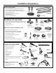
Installation Instructions STEP 1 CHECK DOOR BALANCE PREPARE HOT WATER LINE • The line may enter from either side, rear or floor within the shaded area shown in Figure F. • The line may pass through the same hole as the electrical cable and drain hose. Or, cut an additional 1-1/2" dia. hole to accommodate the water line. If power cord with plug is used, water line must not pass through power cord hole. • With dishwasher on the wood skid, check the door balance by opening and closing the door.
Installation Instructions STEP 2 REMOVE WOOD BASE, INSTALL LEVELING LEGS IMPORTANT – Do not kick off wood base! Damage will occur. • Move the dishwasher close to the installation location and lay it on its back. • Remove the four leveling legs on the underside of the wood base with an adjustable wrench or 15/16" socket. • Discard base. Figure J • Screw leveling legs back into the dishwasher frame, approximately 1/4" from frame as shown. STEP 3 REMOVE TOEKICK • Remove the two toekick screws.
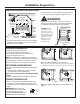
Installation Instructions STEP 6 POSITION WATER LINE AND HOUSE WIRING STEP 8 SLIDE DISHWASHER PARTIALLY INTO CABINET • Position water supply line and house wiring on the floor of the opening to avoid interference with base of dishwasher and components under dishwasher. DO NOT PUSH AGAINST FRONT PANEL WITH KNEES. DAMAGE WILL OCCUR. • Slide dishwasher into the opening a few inches at a time.
Installation Instructions STEP 10 POSITION DISHWASHER UNDER COUNTERTOP • Push the dishwasher into the cabinet. • Push at the sides with your hands. Do not use your knee against the door since door damage will occur. • Check that the tub insulation blanket does not get “bunched-up” or interfere with the springs as you slide it into the cabinet. • Center the dishwasher in the opening.
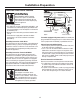
Installation Instructions • Level the dishwasher by adjusting the four leveling legs individually. • If adjustment to the right rear leveling leg is required, gain access by loosening junction box bracket screw (through the access hole) and rotate bracket clockwise. STEP 11 LEVEL DISHWASHER IMPORTANT – Dishwasher must be level for proper dish rack operation and wash performance. • Place level on door and rack track inside the tub as shown to check that the dishwasher is level.
Installation Instructions STEP 13 CONNECT WATER SUPPLY Connect water supply line to 90° elbow. • Slide compression nut, then ferrule over end of water line. • Insert water line into 90° elbow. • Slide ferrule against elbow and secure with compression nut. IMPORTANT – Check to be sure that door spring does not rub or contact the fill hose or Figure CC water supply line. Test by opening and closing the door. Re-route the lines if a rubbing noise or interference occurs.
Installation Instructions STEP 16 PRE-TEST CHECK LIST Review this list after installing your dishwasher to avoid charges for a service call that is not covered by your warranty. Check to be sure power is OFF. Open door and remove all foam and paper packaging. Locate the Owner’s Manual in the literature package. Read the Owner’s Manual for operating instructions. Check door opening and closing.
Installation Instructions STEP 17 DISHWASHER WET TEST Turn on power supply (or plug power cord into outlet, if equipped). STEP 18 REPLACE TOEKICK • Place toekick against the legs of the dishwasher. Start the unit to check for leaks. PDW8100-PDW8800 Series: – Latch door – Push RINSE ONLY pad – Push START/RESET pad PDW9200-PDW9800 Series: – Push RINSE ONLY pad – Push START/RESET pad – Close door Push “Rinse Only” button. Push start/reset pad once.
TM PDW9700JII – GE Profile™ Fully Integrated Built-In Dishwasher Installation Information (in inches) Built-In Dishwasher Dimensions (in inches) Custom Panel for Model PDW9700JII Dishwasher comes panel-ready. 24††† 24 Countertop 90° 22-1/2 24" MIN. 4 90° Electrical wiring is 3" from cabinet 4 4 27-1/2 33-13/16" MIN. adj.
Trim Around Dotted Line Top of Panel Top of Panel Trim Around Dotted Line 2-9/32" 2-9/32" 11-5/16" 11-5/16" Drill 3/32" Pilot Hole 3/32" Deep Drill 3/32" Pilot Hole 3/32" Deep STEP 5 INSTALL CUSTOM HANDLE 3/4" Thick Custom Panel Template Instructions For PDW9700J Series The custom panel should be sized to your installation situation. See Step 1. For easier installation the custom panel and custom handle should be attached before installing the dishwasher.
TM PDW9700JII – GE Profile™ Fully Integrated Built-In Dishwasher TIME Specification Created 7/03 250202 REMAINI NG