
Installation Guide

GEH 3895F
INSTRUCTIONS
PERMA•GARD™ LUMINAIRE
READ THOROUGHLY BEFORE INSTALLING
THE OPERATING TEMPERATURE “T-CODE” LISTED
FOR THIS LUMINAIRE IS BASED ON THE FOLLOW-
ING BULB SIZES. USE OF OTHER THAN THESE
MAY RESULT IN A HIGHER OPERATING TEMPERA-
TURE AND COULD RESULT IN A HAZARDOUS
CONDITION.
LAMP TYPE WATTAGE BULB SIZE
HIGH PRESSURE SODIUM 70,100,150 ED 23 1/2
METAL HALIDE/MERCURY 175,250 ED28
GENERAL
This luminaire is designed for application in extremely
corrosive environments. Certain units, when properly labeled,
may be used in hazardous location environments and
outdoor saltwater marine locations as specified on the
nameplate.
CAUTION: When installing the luminaire in hazard-
ous locations check the operating temperature
limits prior to installation to be sure it conforms to
the environmental temperature restrictions and NEC
classifications.
UNPACKING
The ballast assembly, optical assembly, and mounting assembly
are separately packaged. Check to verify that the correct material
has been received. The components have been properly packed so
that no parts should have been damaged during transit. Inspect to
confirm.
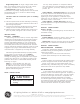
INSTALLATION MOUNTING-CONDUIT
inch) by threading mounting assembly onto conduit hand
tight. Loosen locking nut until it disengages from mounting
hub and is free to move up conduit (See Figure A). This
exposes wrench flats and set screw provided on hanger hub.
Fully tighten hub onto conduit and tighten set screw to lock
hanger hub to conduit. (See Figure B).
Connect ground lead to screw provided in mounting hub.
Connect supply wires to electrical disconnect. Refasten
disconnect into mounting hub (See Figure C).
With Glass Globe With Reflector Assembly
CAUTION
Unit will fall if not installed properly
• Follow installation instructions
WARNING
Risk of electric shock
• Turn power off before servicing
– see instructions
WIRING
Make all electrical connections in accordance with
the National Electrical Code and any applicable local
code requirements.
Verify that supply voltage is correct by comparing it
to nameplate.
NOTE: When changing voltage on reconnectable
units, move only the lead with the insulated connec-
tor.
STANCHION ARM AND WALL BRACKET
INSTALLATION
Attached stanchion arm to a matching size pipe of 1
1/4 in. or 1 1/2 in. N.P.T. and tighten set screw.
Wall bracket should be attached to a mounting surface by
using four clearance holes in bracket flange. For wiring
remove appropriate plug to gain access to wiring compart-
ment. Electrical disconnect is prewired by factory. To install
ballast housing refer to ballast assembly installation instruc-
tions.
Remove electrical disconnect from hanger hub. Fasten the
mounting assembly to matching size conduit (3/4-in. or 1-
Figure A Figure B Figure C
These instructions do not purport to cover all details or variations in equipment nor to provide for every possible contingency to be met in connection with installation, operation or
maintenance. Should further information be desired or should particular problems arise which are not covered sufficiently for the purchaser’s purposes, the matter should be referred
to GE Lighting Solutions.
g
GE
Lighting Solutions