Profile Performance Series ™ system Water Softening GE Appliances Safety Instructions Owner’s Manual & Installation Instructions Proper installation . . . . . . . . . . . .3 Installation Instructions PNSF39Z01 Drain connections . . . . . . . . . .7, 8 Important recommendations . .4 Installation instructions . . . . . .4-6 Planning and location . . . . . . . . .5 Programming the control . . . . . .9 Sanitizing . . . . . . . . . . . . . . . . . .10 Specifications and dimensions . . . . . . . . . . .
Congratulations! You are Now Part of the GE Family. Welcome to the GE family. We’re proud of our quality products and we are committed to providing dependable service. You’ll see it in this easy-to-use Installation and Owner’s Manual and you’ll hear it in the friendly voices of our customer service department. Best of all, you’ll experience these values each time you use the water system. That’s important, because your new system will be part of your family for many years.
IMPORTANT SAFETY INFORMATION. READ ALL INSTRUCTIONS BEFORE USING. WARNING! For your safety, the information in this manual must be followed to minimize the risk of electric shock, property damage or personal injury. SAFETY PRECAUTIONS ■ Check and comply with your state and local codes. You must follow these guidelines. ■ Use care when handling the water softening system. Do not turn upside down, drop, drag, or set on sharp protrusions.
Installation instructions. CAUTION: Certain plumbing skills are needed for installation. If you are unsure about any part of the installation of this product, consult a professional plumber. Unpacking and Inspection Be sure to check the entire softener for any shipping damage or parts loss. Also note damage to the shipping cartons. Contact the transportation company for all damage and loss claims. The manufacturer is not responsible for damages in transit.
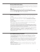
Plan How You Will Install the Softener You must first decide how to run in and out pipes to the softener. Look at the house main water pipe at the point where you will connect the softener. Is the pipe soldered copper, glued plastic, or threaded galvanized? What is the pipe size? WARNING: Use only lead-free solder and flux to prevent lead poisoning. See Typical Installation Illustration, Fig.1. Use this as a guide when planning your particular installation.
Installation instructions. Typical Installation Illustration Fig. 1 MAIN WA TER PIPE Soft water Hard water Hard water to outside faucets 120-volt outlet CROSS-OVER Use if water supply flows from the left. Include single or 3-valve bypass. Union (2) (not supplied) Nut (2) Copper tube, 3/4″ (2) 24V transformer Washer (2) Hard water INLET Brinewell NOTE: See Drain Hose Connections section. Bypass Valve • pull out for service • push in for bypass NOTE: Threads on the bypass valve are 1” male pipe.
Step-by-step installation instructions. • Turn off the gas or electric supply to the water heater, in the possibility that the water heater may be drained while draining pipes. Clip Fig. 3A • Turn off the water supply to pipes to be cut and drain the house water pipes. Outlet • Open both hot and cold faucets. 1. INSTALL BYPASS VALVE • Remove plastic shipping plug and wire from valve outlet. NOTE: Be sure the turbine and support are firmly in place in the valve outlet.
Step-by-step installation instructions. 4A. CONNECTING A RIGID VALVE DRAIN TUBE Fig. 4A 1/4″ NPT threads 1/2″ O.D. • To adapt a copper drain tube to the softener, use a hacksaw to cut the barbed end copper tube (not from the drain fitting as shown in Fig. 4A. Rotate the drain fitting so the cutting Barbs furnished) blade clears the valve housing to prevent damage to valve. Buy a compression fitting (1/4″ female pipe thread x 1/2″ O.D. tube) and needed tubing from your local hardware store. Clip 5.
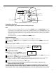
TOUCH or HOLD button UP (+) button RECHARGE TONIGHT RECHARGE NOW TOUCH or HOLD TIME HARDNESS SET Set button DOWN (-) button Display DATA REMAINING CAPACITY FLOW RATE GPM GALLONS TODAY AVG. DAILY GALLONS DATA button Programming the Control Timer settings required—upon installation and after an extended power outage. NOTE: • When the transformer is plugged into the electrical outlet, 12:00 AM is flashing and PRESENT TIME show in the upper display area. Program the timer as instructed below.
Step-by-step installation instructions. Sanitizing Procedures To complete the installation, do the following sanitizing procedures. Care is taken at the factory to keep your water softener clean and sanitary. Materials used to make the softener will not infect or contaminate your water supply and will not cause bacteria to form or grow. However, during shipping, storage, installing and operating, bacteria could get into the softener. For this reason, sanitizing as follows is suggested when installing.
Specifications/Dimensions Model GE Profile Performance PNSF39Z See rating decal, located on the softener Rated Capacity* Amount of high capacity resin (lbs/cu. ft) 52/1.0 Resin tank nominal size (in., dia. x height) 10″ x 35″ Service flow rate (gpm) (see rating label on softener) 10 Water supply maximum hardness (gpg) 110 Water supply maximum clear water iron (ppm) ** 6.6 20-125 Water pressure limits (min.-max.
About the water softener system. Service When the water softening system is providing soft water, it is called “Service.” During service, hard water flows from the house main water pipe into the water softening system. Inside the water softening system resin tank is a bed made up of thousands of tiny, plastic resin beads. As hard water passes through the bed, each bead attracts and holds the hard minerals. This is called ion-exchanging. It is much like a magnet attracting and holding metals.
Breaking a Salt Bridge Sometimes, a hard crust or salt bridge forms in the salt storage area. It is usually caused by high humidity or the wrong kind of salt. When the salt bridges, an empty space forms between the water and salt. Then salt will not dissolve in the water to make brine. If the brine tank is full of salt, it is hard to tell if you have a salt bridge. Salt is loose on top, but the bridge is under it. The following is the best way to check for a salt bridge.
About the water softener system. Cleaning the Nozzle and Venturi Assembly A clean nozzle and venturi is needed for the water softening system to work properly. This small unit makes the suction to move brine from the salt storage area to the resin tank during regeneration. If it becomes plugged with sand, dirt, etc., the water softening system will not work and you will get hard water. To get to the nozzle and venturi, remove the water softening system top cover.
Normal Operation, Timer Display During normal operation, the present time of day and AM or PM show in the control display area. When the demand computer determines a regeneration is needed, RECHARGE TONIGHT begins to flash in the display along with the present time. RECHARGE TONIGHT flashes until the next regeneration start time, then changes to RECHARGE NOW, which flashes until the regeneration is over. The display also shows the current cycle in the regeneration process.
About water softener system. Feature/Service: Automatic Electronic Diagnostics The timer computer has a self-diagnostic function for the electrical system (except input power and water meter). The computer monitors the electronic components and circuits for correct operation. If a malfunction occurs, an error code appears in the timer display. The chart on Error Codes shows the error codes that could appear and possible defects for each code.
Timer/Softener, Service Checkout Procedure If you are not getting soft water, and an error code is not displayed, use the procedures below to find the problem. First make the following visual checks.
About water softener system. Service: Manually Initiated Electronic Diagnostics 1 To enter diagnostics, press and hold the DATA button until the display appears as shown. NOTE: If the softener is in the middle of a regeneration, top part of the display shows the cycle of regeneration and minutes of the cycle remaining. If two cycle names are flashing, the valve is in transition between the cycles.
Service: Manually Advance Regeneration Check This check verifies proper operation of the valve motor, brine tank fill, brine draw, regeneration flow rates and other controller functions. First, make the initial checks and the manually initiated electronic diagnostics. NOTE: The face plate display must show a steady time (not flashing). 1 Press the TOUCH or HOLD button and hold for three seconds. RECHARGE NOW begins to flash as the water softening system enters the fill cycle of regeneration.
About water softener system. Service: Regeneration and Heavy Duty Backwash NOTE: Each of the following functions has a factory set default value. The defaults are: Regeneration start time –2:00AM ; Maximum days between regenerations –0 (display shows dY–); Heavy duty backwash –OFF. The defaults are suitable for most installations. However, depending on water supply quality, household peak water use hours, etc., adjustment is available to meet specific needs. To make a change, read and do the following.
Setting: Model Code, 12 or 24 Hour Clock and Gallons or Liters Measured Model Code: The timer must have the right model code set to operate the water softening system correctly. The correct code setting is PL31. If PL-- is flashing in the display, do steps 3, 4, 6 and 8 below. To check for the correct code setting for your model, and to reset it if needed, do steps 1, 2, 3, 4, 6 and 8 below. NOTE: The hour clock and water measure have factory set default values.
Care and cleaning of the water softening system. Checking the Salt Storage Level and Refilling Brine (salt dissolved in water) is needed for each and every regeneration. The water for making brine is metered into the salt storage area by the water softening system valve and control. However, you must keep the tank supplied with salt. When to refill with salt: Check the salt level a few weeks after you install the water softening system and every week after that.
Before you call for service… Troubleshooting Tips Save time and money! Review the chart on this page first and you may not need to call for service. NO SOFT WATER – Most Common Problems: Check the following before calling for service • Salt in softener...at least 1/3 full. • By pass valve in “Service” position. Knob should be in the OUT position. • Check hardness setting in control. Verify hardness of supply water. Water hardness can vary throughout the year (see Programming the Control section).
Before you call for service… Troubleshooting Tips Problem Possible Causes What To Do Water hard sometimes Using hot water while the water softening system is regenerating • Avoid using hot water during water softening system regenerations because the water heater will refill with hard water. See Automatic Hard Water Bypass During Regeneration section. Control hardness number setting too low • Press and release the SET button until HARDNESS shows in the display.
Problem Possible Causes What To Do Salty tasting water after installation Insufficient backwash and rinse time •Increase backwash time. See the Service: Regeneration and Heavy Duty Backwash section. Low water pressure •Check pressure; should be minimum 20 psi. Restricted drain hose •Clean and reconnect hose. Resin beads showing up in drinking water and sink Cracked distributor •Call for service. Sounds you might hear Running water from the unit into a drain •This is normal.
Notes.
GE Service Protection Plus™ GE, a name recognized worldwide for quality and dependability, offers you Service Protection Plus ™—comprehensive protection on all your appliances— No Matter What Brand! Benefits Include: • Backed by GE • All brands covered • Unlimited service calls • All parts and labor costs included • No out-of-pocket expenses • No hidden deductibles • One 800 number to call We’ll Cover Any Appliance. Anywhere. Anytime.
Consumer Product Ownership Registration Dear Customer: Thank you for purchasing our product and thank you for placing your confidence in us. We are proud to have you as a customer! Follow these three steps to protect your new appliance investment: 1 2 3 Complete and mail your Consumer Product Ownership Registration today. Have the peace of mind of knowing we can contact you in the unlikely event of a safety modification. After mailing the registration below, store this document in a safe place.
Parts list.
Parts list.
Parts catalog. GENERAL ELECTRIC PARTS CATALOG PNSF39Z01 REF. NO. 0003 0004 0005 0007 0008 0009 0010 0011 0012 0013 0014 0015 0016 0018 0020 0021 0022 0023 0024 0025 0026 0027 0028 0029 0030 0031 0032 0033 0034 0035 0036 0037 0038 0055 0056 0998 0999 PART NO.
Parts catalog. GENERAL ELECTRIC PARTS CATALOG PNSF39Z01 REF. NO. 0025 0101 0102 0103 0104 0105 0106 0107 0108 0109 0110 0111 0112 0114 0115 0116 0117 0118 0119 0120 0121 0122 0123 0130 0132 0133 0134 0135 0136 0137 0138 0139 0140 0141 0142 0143 0144 0145 0146 0147 0150 0151 0152 0153 32 PART NO.
Notes.
Notes.
GE Water Softening System Warranty All warranty service provided by our Factory Service Centers, or an authorized Customer Care® technician. For service, call 800-GE-CARES. For The Period Of: GE Will Replace: One Year From the date of the original purchase Three Years From the date of the original purchase Ten Years From the date of the original purchase Any part of the Water Softening System which fails due to a defect in materials or workmanship.
Service Telephone Numbers. GE Answer Center® 800.626.2000 The GE Answer Center® is open 24 hours a day, 7 days a week. OR Visit our Website at: www.geappliances.com In-Home Repair Service 800-GE-CARES (800-432-2737) Expert GE repair service is only a phone call away. Special Needs Service 800.626.2000 800-TDD-GEAC (800-833-4322) GE offers, free of charge, a brochure to assist in planning a barrier-free kitchen for persons with limited mobility.