
Installation guide


Installation Instructions
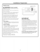
[] INSTALL REMOTE SWITCH
AWARNING: SHOCK HAZARD
Disconnect electrical power from unit before
beginning switch installation. Failure to do so could
result in personal injurg or damage to the electrical
controls.
WARNING: BURNHAZARD
The remote switch must be located so that it can be
operated without reaching over the cooktop. Failure
to do so mug result in ignition of clothing which could
cause serious injurg or death.
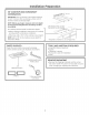
Determine the location for the remote switch.
, The remote switch should be located so that the
vertical distance from the floor to the remote
switch is less than 48" and more than 15".
, The remote switch harness is 68" long and should
be installed so that it is not pinched and is awag
from moving parts.
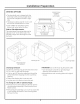
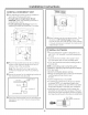
Connect Remote Switch to Remote Harness
• Thread the remote harness through the 1/2"-dia.
hole and attach the harness connector to the
remote connector.
Remove the paper backing on the remote switch
foam piece and mount the remote switch on the
countertop such that the switch connectors stag
located in the 1/2"-dim. hole.
• Stick adhesive wire clamp near the 1/2"-dia. hole
and attach the loose wire with a wire tie.
Strain Relief
(Adhesive wire
clamp with tie)
Control
Box
Hating Connectors
Remote Harness
Remote Switch
Foam Piece With
Adhesive Mounting" _
Surface
_ _-- !/2"-Dio. Hole
Strain Relief I_
(Adhesive wire clamp _, _
withtie) _ _ _x___
f If )? -Remote
\ II :_ Horness_ 1/2"-Dia.
/ II ( Remote
%// switch
_, / F°amtiP_gCserV_heAdhesive
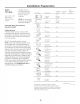
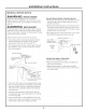
Drill a 1/2"-dia. hole into the desired location. Use
the mounting bracket as a template to locate the
hole accuratelg. Check for interference between
the switch cover, adjacent objects and cooktop/
vent overlaps.
, If switch is mounted into a tile surface, drill the
hole between tiles. Use Iocallg approved caulking
to cover ang gaps.
, If the remote switch is not installed on the coun-
tertop, ensure that it is installed in a location that
meets local codes and is easilg accessible.
Connect Wire Lead to Control Box
, Connect the mating wire ends.
Place the adhesive wire clumps (provided) near
the mating connector.
Keep approximatelg ]"-long wire and attach
the wire to the clamp with a wire tie. This will act
as a strain relief.
12