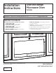
Installation Instructions 2YHU WKH 5DQJH 0LFURZDYH 2YHQ PVM9005 Questions? Call 800.GE.CARES (800.432.2737) or Visit our Website at: GEAppliances.com BEFORE YOU BEGIN Read these instructions completely and carefully. IMPORTANT – Save these instructions for local inspector’s use. IMPORTANT – Observe all governing codes and ordinances. Note to Installer – Be sure to leave these instructions with the consumer. Note to Consumer – Keep these instructions for future reference.
Installation Instructions C Outside Back Exhaust.................................. 21-24 CONTENTS Installation Overview ................................ 21 General information Important Safety Instructions........................................ 3 Preparing Rear Wall for Outside Back Exhaust ................................21 Electrical Requirements .................................................. 3 Attach Mounting Plate to Wall .......... 21, 22 Tools You Will Need ................................
Installation Instructions IMPORTANT SAFETY INSTRUCTIONS A qualified electrician must perform a ground continuity check on the wall receptacle before beginning the installation to ensure that the outlet box is properly grounded. If not properly grounded, or if the wall receptacle does not meet electrical requirements noted (under ELECTRICAL REQUIREMENTS), a qualified electrician should be employed to correct any deficiencies.
Installation Instructions TOOLS YOU WILL NEED #1 and #2 Phillips screwdriver Pencil Carpenter square (optional) Ruler or tape measure and straight edge Tin snips (for cutting damper, if required) Scissors (to cut template, if necessary) Electric drill with ø s, ø s, 1ø2s and 5ø8s drill bits Filler blocks or scrap wood pieces, if needed for top cabinet spacing (used on recessed bottom cabinet installations only) Stud finder Duct and masking tape 3 16 Gloves Safety goggles 7 16 Saw (saber, hole
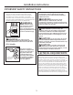
Installation Instructions HOOD EXHAUST NOTE: 5HDG WKHVH QH[W WZR SDJHV RQO\ LI \RX SODQ WR YHQW \RXU H[KDXVW WR WKH RXWVLGH ,I \RX SODQ WR UHFLUFXODWH WKH DLU EDFN LQWR WKH URRP SURFHHG WR SDJH 6. %HORZ DUH H[DPSOHV RI 2XWVLGH 7RS ([KDXVW DQG 2XWVLGH %DFN ([KDXVW GXFW V\VWHP OD\RXWV 1RWH WKH SRVLWLRQ RI WKH PLFURZDYH RYHQ UHODWLYH WR WKH GXFW V\VWHP 2876,'( 723 (;+$867 (;$03/( 21/< The following chart describes an example of one possible ductwork installation.
Installation Instructions NOTE: If you need to install ducts, note that the total duct length of 31ø4s x 10s rectangular or 6s diameter round duct VKRXOG QRW H[FHHG HTXLYDOHQW IHHW Outside ventilation requires a HOOD EXHAUST DUCT. Read the following carefully: NOTE: It is important that venting be installed using the most direct route and with as few elbows as possible. This ensures clear venting of exhaust and helps prevent blockages. $OVR PDNH VXUH GDPSHUV VZLQJ IUHHO\ DQG QRWKLQJ LV EORFNLQJ WKH
Installation Instructions PARTS INCLUDED '$0$*( ² 6+,30(17 INSTALLATION ADDITIONAL PARTS PART ,I WKH XQLW LV GDPDJHG LQ VKLSPHQW return the unit to the store in which it was bought for repair or replacement. ,I WKH XQLW LV GDPDJHG E\ WKH FXVWRPHU repair or replacement is the responsibility of the customer. ,I WKH XQLW LV GDPDJHG E\ WKH LQVWDOOHU (if other than the customer), repair or replacement must be made by arrangement between customer and installer.
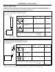
Installation Instructions MOUNTING SPACE 17 5/8s max. 16-½s 30s 2s 30s min. Bottom edge of cabinet needs to be 30s or more from the cooking surface or top surface of gas grates whichever is taller Backsplash 66s or more from the floor to the top of the microwave oven 8 NOTES: The space between the cabinets must be 30s wide and free of obstructions. If you are going to vent your microwave oven to the outside, see Hood Exhaust Section for exhaust duct preparation.
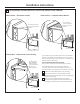
Installation Instructions 1 PLACEMENT OF THE MOUNTING PLATE A REMOVING THE MICROWAVE 29(1 )520 7+( &$5721 REMOVING THE MOUNTING PLATE B FINDING THE WALL STUDS 1 Open the box and fold back all four carton flaps fully against the carton sides. Remove the following items from the protective foam: installation instructions, filters, exhaust adaptor, damper, and the small hardware bag. Do not remove the foam protecting the front of the microwave oven.
Installation Instructions C DETERMINING MOUNTING PLATE LOCATION UNDER YOUR CABINET Plate Position – recessed cabinet bottom Plate Position – flat bottom cabinet Mounting Plate Tabs Touching the Back Frame of the Cabinet Mounting Plate Tabs Touching the Cabinet Bottom 30s to Cooktop At least 30s, up to 36s 3ODWH 3RVLWLRQ ² FDELQHW ZLWK IURQW RYHUKDQJ Your cabinets may have decorative trim that interferes with the microwave oven installation.
Installation Instructions D ALIGNING THE MOUNTING PLATE 30” Hole B Draw a Vertical Line on Wall from Center of Top Cabinet Hole A Hole D Hole C Area E CAUTION: Notch :HDU JORYHV WR DYRLG FXWWLQJ ILQJHUV RQ VKDUS HGJHV 1 Draw a vertical line on the wall at the center of the 30s wide space. 2 Use the mounting plate as the template for the rear wall.
Installation Instructions 2 INSTALLATION TYPES &KRRVH $ % RU & This microwave oven is designed for adaptation to the following 3 types of ventilation: $ 5HFLUFXODWLQJ 1RQ 9HQWHG 'XFWOHVV % 2XWVLGH 7RS ([KDXVW 9HUWLFDO 'XFW & 2XWVLGH %DFN ([KDXVW +RUL]RQWDO 'XFW A 127( 6HOHFW WKH W\SH RI YHQWLODWLRQ UHTXLUHG IRU \RXU installation and proceed to that section.
Installation Instructions A RECIRCULATING 1RQ 9HQWHG 'XFWOHVV INSTALLATION OVERVIEW A1. Attach Mounting Plate to Wall A2. Prepare Top Cabinet A3. Adjust Blower Motor A4. Install Charcoal Filter A5. Mount the microwave oven A6. Installing/Replacing the Charcoal Filter Without Access to Top Screws and the Unit Has Already Been Mounted. 3 Place the mounting plate against the wall and insert the toggle wings into the holes in the wall to mount the plate.
Installation Instructions A3 ADJUST BLOWER MOTOR A3 $'-867 %/2:(5 02725 FRQW Fan Blades 1 Remove the screws holding the blower unit and the screws securing the blower plate. Remove the blower plate from the outer case by sliding it toward the back of the microwave and pulling up. Blower Motor Screws Wires Back of Mircrowave Blower Plate 3 Roll the blower so that fan blade openings are facing the top of the oven. Place the blower back into the opening.
Installation Instructions A4 INSTALLING THE CHARCOAL FILTER A5 MOUNT THE MICROWAVE OVEN 1 Open the door. 2 Push the “Push” area on charcoal filter cover at center of the grille. CAUTION: 7R DYRLG WKH ULVN RI SHUVRQDO LQMXU\ EDFN LQMXU\ RU RWKHU LQMXULHV GXH WR H[FHVVLYH ZHLJKW RI WKH PLFURZDYH RU SURSHUW\ GDPDJH \RX ZLOO QHHG WZR SHRSOH WR LQVWDOO WKLV PLFURZDYH IMPORTANT: Do not grip or use handle during installation. WARNING: 5LVN RI (OHFWULF 6KRFN &DQ FDXVH LQMXU\ RU GHDWK ,I LQVWDOOLQJ X
Installation Instructions A5 MOUNT THE MICROWAVE OVEN FRQW 1 1 3 Insert 3 self-aligning screws ( ø4s-28 x 2 ø4”) through outer top cabinet holes. Turn two full turns on each screw. Cabinet Front Cabinet Bottom Shelf Filler Block Equivalent to Depth of Cabinet Recess This distance can NOT exceed 2” to ensure proper installation Self-Aligning Screw Microwave Oven Top Self-Aligning Screws 4 Tighten the three screws to the top of the microwave oven.
Installation Instructions B OUTSIDE TOP EXHAUST 9HUWLFDO 'XFW INSTALLATION OVERVIEW B1. Attach Mounting Plate to Wall B2. Prepare Top Cabinet B3. Adjust Blower Motor B4. Install Exhaust Adaptor B5. Mount Microwave Oven B6.
Installation Instructions B3 $'-867 %/2:(5 02725 FRQW B2 USE TOP CABINET TEMPLATE FOR PREPARATION OF TOP CABINET Rotate 90° You need to drill holes for the top support screws, a hole large enough for the power cord to fit through, and a cutout large enough for the exhaust adaptor. Back of Mircrowave 3 Roll the blower so that fan blade openings are facing the top of the oven. Place the blower back into the opening. Fan Blades Wires Read the instructions on the TOP CABINET TEMPLATE.
Installation Instructions B5 MOUNT THE MICROWAVE OVEN B4 ASSEMBLE AND INSTALL ADAPTOR Blower Plate Damper CAUTION: 7R DYRLG WKH ULVN RI SHUVRQDO LQMXU\ EDFN LQMXU\ RU RWKHU LQMXULHV GXH WR H[FHVVLYH ZHLJKW RI WKH PLFURZDYH RU SURSHUW\ GDPDJH \RX ZLOO QHHG WZR SHRSOH WR LQVWDOO WKLV PLFURZDYH 1 Place the microwave oven in its upright position, with the top of the unit facing up and the front of the unit facing toward you.
Installation Instructions B6 CONNECTING DUCTWORK B5 MOUNT THE MICROWAVE OVEN FRQW 3 Insert a self-aligning screw through top-center cabinet hole. Temporarily secure the microwave oven by turning the screw at least two full turns after the threads have engaged. (It will be completely tightened later.) Insert 2 self-aligning screws (1ø4s-28 x 2 1ø4s) through outer top cabinet holes. Turn two full turns on each screw. House Duct 1 Extend the house duct down to connect to the exhaust adaptor.
Installation Instructions C OUTSIDE BACK EXHAUST +RUL]RQWDO 'XFW INSTALLATION OVERVIEW C1. Prepare Rear Wall C2. Attach Mounting Plate to Wall C3. Prepare Top Cabinet C4. Adjust Blower C5. Mount the Microwave Oven C2 ATTACH THE MOUNTING PLATE TO THE WALL C1 PREPARING THE REAR WALL FOR OUTSIDE BACK EXHAUST You need to cut an opening in the rear wall for outside exhaust. Attach the plate to the wall using toggle bolts. At least one wood screw must be used to attach the plate to a wall stud.
Installation Instructions C2 ATTACH THE MOUNTING PLATE TO THE WALL cont C4 ADAPTING BLOWER FOR OUTSIDE BACK EXHAUST 1 Remove the blower motor screws that holds the blower plate to the microwave oven. Slide the plate toward the back of the microwave and lift up to remove.
Installation Instructions C4 ADAPTING BLOWER FOR OUTSIDE BACK EXHAUST cont. C5 MOUNT THE MICROWAVE OVEN 6 Gently place the fan back into the cavity with the exhaust portion of the fan at the top and facing the back of the unit. CAUTION: 7R DYRLG WKH ULVN RI SHUVRQDO LQMXU\ EDFN LQMXU\ RU RWKHU LQMXULHV GXH WR H[FHVVLYH ZHLJKW RI WKH PLFURZDYH RU SURSHUW\ GDPDJH \RX ZLOO QHHG WZR SHRSOH WR LQVWDOO WKLV PLFURZDYH IMPORTANT: Do not grip or use handle during installation.
Installation Instructions C5 MOUNT THE MICROWAVE OVEN FRQW 3 Insert a self-aligning screw through top-center cabinet hole. Temporarily secure the microwave oven by turning the screw at least two full turns after the threads have engaged. (It will be completely tightened later.) Insert 2 self-aligning screws (1ø4s-28 x 2 1ø4s) through outer top cabinet holes. Turn two full turns on each screw.
Installation Instructions BEFORE YOU USE YOUR MICROWAVE OVEN 1 Make sure the microwave oven has been installed according to instructions. 6 Read the Quick Use & Care. QUICK RE USE & CA 2 Remove all packing material from the microwave oven. 3 Install turntable and turntable ring in cavity. 4 Replace house fuse or turn breaker back on. 5 120 V Models: Plug power cord into a dedicated 15- to 20-amp electrical outlet. 7 Ensure proper ground exists before use.
Installation Instructions Printed in China 26
Instrucciones de Instalación Horno microondas para colocar encima de la estufa PVM9005 ¿Preguntas? Llame a 800.GE.CARES (800.432.2737) o visite nuestro sitio web en: GEAppliances.com ANTES DE COMENZAR Lea estas instrucciones en su totalidad y atentamente. IMPORTANTE – Conserve estas instrucciones para uso del inspector local. IMPORTANTE – Cumpla con todos los códigos y ordenanzas gubernamentales. Nota para el Instalador – Asegúrese de entregar estas instrucciones la Consumidor.
Instrucciones de Instalación C Escape de Salida Trasero ............................ 21-24 CONTENIDOS Visión General de la Instalación ...............21 Información General Instrucciones Importantes de Seguridad .................... 3 Preparación de la Pared Trasera para el Escape de Salida Trasero ............21 Requisitos Eléctricos ....................................................... 3 Adjunte la Placa de Montaje a la Pared .. 21, 22 Herramientas Que Necesitará .................................
Instrucciones de Instalación INSTRUCCIONES IMPORTANTES DE SEGURIDAD Un electricista calificado deberá realizar un control de la continuidad de la conexión a tierra en el receptáculo de la pared antes de comenzar con la instalación, a fin de asegurar que la caja del tomacorriente esté correctamente conectada a tierra.
Instrucciones de Instalación HERRAMIENTAS NECESARIAS Destornillador Phillips nº1 y nº2 Lápiz Escuadra de carpintero (opcional) Regla o cinta métrica y extremo recto Tijeras para hojalata (para cortes en reguladores, si se requiere) Tijeras (para cortar plantillas, si es necesario) Taladro eléctrico con brocas de 3/15”, 7/16”, 1/2”, y 5/8” Guantes Gafas de seguridad Sierra (sable, agujero o cerradura) Detector de montantes Nivel 4 Bloques de llenado o piezas de fragmentos de madera, si son necesar
Instrucciones de Instalación CAMPANA DE ESCAPE 127$ /HD ODV GRV VLJXLHQWHV SiJLQDV VyOR VL SODQHD YHQWLODU VX HVFDSH GHVGH OD SDUWH H[WHULRU 6L SODQHD KDFHU TXH HO DLUH YXHOYD D FLUFXODU HQ OD KDELWDFLyQ SDVH D OD SiJLQD $ FRQWLQXDFLyQ ILJXUDQ HMHPSORV GH GLDJUDPDV GHO VLVWHPD GHO FRQGXFWR GHO (VFDSH GH 6DOLGD 6XSHULRU \ GHO (VFDSH GH 6DOLGD 7UDVHUR 2EVHUYH OD SRVLFLyQ GHO KRUQR PLFURRQGDV UHODWLYD DO VLVWHPD GH WXEHUtDV ESCAPE DE SALIDA SUPERIOR (SÓLO EJEMPLO) En el siguiente cuadro se describ
Instrucciones de Instalación NOTA: Si necesita instalar tuberías, deberá observar que la longitud total de una tubería rectangular de 3 1/4” x 10” o una circular de 6” de diámetro QR GHEHUi VXSHUDU ORV SLHV GH HTXLYDOHQFLD La ventilación externa requiere un CONDUCTO DE SALIDA DE LA CAMPANA. Lea la siguiente información detenidamente. NOTA: Es importante que la ventilación sea instalada utilizando la ruta más directa y con la menor cantidad de codos posible.
Instrucciones de Instalación PARTES INCLUIDAS '$f2 ² (19Ë2 INSTALACIÓN PIEZAS ADICIONALES 6L OD XQLGDG VH GDxD GXUDQWH HO HQYtR devuelva la unidad a la tienda donde fue comprada para su reparación o reemplazo. Si la unidad es dañada por el cliente, la reparación o reemplazo es responsabilidad del cliente. 6L OD XQLGDG HV GDxDGD SRU HO LQVWDODGRU (si no es el cliente), la reparación o reemplazo deberá ser realizado por arreglo entre el cliente y el instalador.
Instrucciones de Instalación ESPACIO DE MONTAJE Máx. de 17 5/8s 16-½s 30s 2s Mín. de 30s La parte inferior del gabinete necesita estar a 30” o más de la superficie de cocinado o de la parte superior de las parrillas de gas, cualquiera que sea más alta. Tablero posterior 66” o más desde el piso hasta la parte superior del horno microondas 8 NOTAS: El espacio entre los gabinetes debe ser de 30” de ancho y estar libre de obstrucciones.
Instrucciones de Instalación 1 COLOCACIÓN DEL PLATO DE MONTAJE A RETIRO DEL HORNO MICROONDAS '( /$ &$-$ 5(7,52 '(/ 3/$72 DE MONTAJE B BÚSQUEDA DEL MONTAJE DE PARED 1 Abra la caja y vuelva a doblar las cuatro lengüetas de la caja completamente contra los costados de la caja. Retire los siguientes artículos de la gomaespuma protectora: instrucciones de instalación, filtros, adaptador del escape, regulador, y la caja pequeña de piezas. No retire la gomaespuma que protegé el frente del horno microondas.
Instrucciones de Instalación C DETERMINACIÓN DE LA PLACA DE MONTAJE DEBAJO DE SU GABINETE 3RVLFLyQ GH OD 3ODFD ² JDELQHWH LQIHULRU KXHFR 3RVLFLyQ GH OD 3ODFD ² JDELQHWH LQIHULRU SODQR Las Lengüetas de la Placa de Montaje Tocan la Estructura Inferior del Gabinete Las lengüetas de la Placa de Montaje Tocan la Parte Inferior del Gabinete 30” a la Placa de Cocción Por lo menos 30”, hasta 36” 3RVLFLyQ GH OD 3ODFD ² JDELQHWH FRQ IUHQWH saliente Es posible que sus gabinetes posean bordes decorativos que i
Instrucciones de Instalación D ALINEE LA PLACA DE MONTAJE 30” Hole B Dibuje una Línea Vertical en la Pared desde el Centro a la Parte Superior del Gabinete Agujero A Hole D Agujero C Área E PRECAUCIÓN Ranura 8VH JXDQWHV SDUD HYLWDU FRUWHV GH dedos en extremos puntiagudos. 1 Dibuje una línea vertical en la pared en el centro del espacio de 30” de ancho. 2 Use la placa de montaje como plantilla para la pared trasera.
Instrucciones de Instalación 2 TIPOS DE INSTALACIÓN (Elija A, B o C) Este horno microondas está diseñado para ser adaptado a los siguientes 3 tipos de ventilación: A. Recirculación (Sin Conductos no Ventilados) B. Escape Exterior Superior (Conducto Vertical) & (VFDSH ([WHULRU 7UDVHUR &RQGXFWR +RUL]RQWDO A 127$ 6HOHFFLRQH HO WLSR GH YHQWLODFLyQ UHTXHULGD SDUD VX LQVWDODFLyQ \ SURFHGD D GLFKD VHFFLyQ RECIRCULACIÓN (SIN CONDUCTOS NO VENTILADOS) B ESCAPE EXTERIOR SUPERIOR (CONDUCTO VERTICAL) El Ada
Instrucciones de Instalación A RECIRCULACIÓN (Sin Conductos No Ventilados) VISIÓN GENERAL DE LA INSTALACIÓN A1. ADHERA LA PLACA DE MONTAJE A LA PARED A2. USE LA PLANTILLA DEL GABINETE SUPERIOR PARA LA PREPARACIÓN DEL GABINETE SUPERIOR A3. AJUSTE EL MOTOR DEL CALENTADOR A4. CÓMO INSTALAR EL FILTRO DE CARBÓN A5. MONTE EL HORNO MICROONDAS A6.
Instrucciones de Instalación A3 AJUSTE EL MOTOR DEL CALENTADOR A3 AJUSTE EL MOTOR DEL CALENTADOR (cont.) 1 Retire los tornillos que sostienen la unidad del calentador y los tornillos que aseguran el plato calentador. Retire el plato calentador de la caja externa, deslizando la misma hacia la parte trasera del horno microondas y empujando hacia arriba.
Instrucciones de Instalación A4 INSTALLING THE CHARCOAL FILTER A5 MONTE EL HORNO MICROONDAS 1 Abra la puerta. 2 Presione el área “Presionar” en la tapa del filtro de carbón en el centro de la parrilla.
Instrucciones de Instalación A5 MONTE EL HORNO (cont.) 3 Inserte 3 tornillos autoalineantes (1/4” – 28 x 2 ¼”) a través de los agujeros del gabinete superior externo. Dé dos giros completos a cada tornillo.
Instrucciones de Instalación B ESCAPE SUPERIOR EXTERIOR (Conducto Vertical) VISIÓN GENERAL DE LA INSTALACIÓN B1. Adjunte la Placa de Montaje a la Pared B2. Prepare el Gabinete Superior B3. Ajuste el Motor del Calentador B4. Instale el Adaptador del Escape B5. Monte el Horno Microondas B6.
Instrucciones de Instalación B3 AJUSTE EL MOTOR DEL CALENTADOR (cont.) B2 USE LA PLANTILLA DEL GABINETE SUPERIOR PARA LA PREPARACIÓN DEL GABINETE SUPERIOR Gire 90° Es necesario que haga agujeros para los tornillos de soporte de la parte superior, un agujero lo suficientemente grande para que el cable de corriente pueda pasar, y un disyuntor lo suficientemente grande para el adaptador del escape.
Instrucciones de Instalación B5 MONTE EL HORNO MICROONDAS B4 ENSAMBLE E INSTALE EL ADAPTADOR Plato Calentador Regulador PRECAUCIÓN: $ ILQ GH HYLWDU HO riesgo de lesión personal (lesión en la espalda u RWUDV OHVLRQHV GHELGR D XQ SHVR H[FHVLYR GHO KRUQR PLFURRQGDV R GDxRV VREUH OD SURSLHGDG GHEHUi contar con la ayuda de dos personas para instalar HVWH KRUQR PLFURRQGDV 1 Coloque el horno microondas en su posición vertical, con la parte superior de la unidad hacia arriba y el frente hacia usted.
Instrucciones de Instalación B6 CONEXIÓN DEL CONDUCTO B5 MONTE EL HORNO MICROONDAS (cont.) 3 Inserte un tornillo autoalineante a través del agujero de la parte superior del centro del gabinete. En forma temporaria asegure el horno dando al tornillo por lo menos dos giros completos una vez que las roscas fueron colocadas. (Más tarde se ajustará completamente.) Inserte 2 tornillos autoalineantes (1/4” – 28 x 2 ¼”) a través de los agujeros del gabinete superior externo. Dé dos giros completos a cada tornillo.
Instrucciones de Instalación C ESCAPE EXTERIOR TRASERO (&RQGXFWR +RUL]RQWDO VISIÓN GENERAL DE LA INSTALACIÓN C1. Prepare la Pared Trasera C2. Adjunte la Placa de Montaje a la Pared C3. Prepare el Gabinete Superior C4. Ajuste el Calentador C5. Monte el Horno Microondas C2 ADHIERA LA PLACA DE MONTAJE A LA PARED C1 PREPARACIÓN DE LA PARED TRASERA PARA EL ESCAPE EXTERNO TRASERO Es necesario cortar una abertura en la pared trasera del escape externo.
Instrucciones de Instalación C2 ADHIERA LA PLACA DE MONTAJE A LA PARED (cont.) C4 ADAPTACIÓN DEL CALEFACTOR PARA EL ESCAPE EXTERIOR TRASERO Para usar tornillos con resorte: Placa de Montaje 1 Retire el tornillo del motor del calentador que sostiene el plato calentador sobre el horno microondas. Deslice el plato hacia la parte trasera del microondas y levante el mismo para retirarlo.
Instrucciones de Instalación C4 ADAPTACIÓN DEL CALEFACTOR PARA EL ESCAPE TRASERO EXTERIOR (cont.) C5 MONTE EL HORNO MICROONDAS 6 De forma suave vuelva a colocar el ventilador en la cavidad con la parte del escape del ventilador arriba y enfrentando la parte trasera de la unidad.
Instrucciones de Instalación C5 MONTE EL HORNO MICROONDAS (cont.) 3 Inserte un tornillo autoalineante a través del agujero de la parte superior del centro del gabinete. En forma temporaria asegure el horno dando al tornillo por lo menos dos giros completos una vez que las roscas fueron colocadas. (Más tarde se ajustará completamente). Inserte 2 tornillos autoalineantes (1/4” – 28 x 2 ¼”) a través de los agujeros del gabinete superior externo. Dé dos giros completos a cada tornillo.
Instrucciones de Instalación ANTES DE USAR EL HORNO MICROONDAS 1 Asegúrese de que el horno microondas haya sido instalado de acuerdo con las instrucciones. 6 Lea la sección de Uso y Cuidado Rápido. QUICK RE USE & CA 2 Retire todos los materiales de embalaje del horno microondas. 3 Instale el plato giratorio y el anillo del plato giratorio en la cavidad. 4 Reemplace el fusible del hogar o vuelva a activar el disyuntor.
Instrucciones de Instalación Impreso en China 26