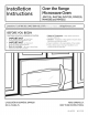
I stall ti I structi Over the Range Microwave Oven JVM7195,JNM7196, DVM7195,PVM9195, PNM9196and PVM9215 i Questions? Call 800.GE.CARES (800.432.2737) or visitourWebsiteat: GEAppliances.com i BEFORE YOU BEGIN Read these instructions • IMPORTANT completely and carefully. Note to Consumer - Sovethese Skill level - Installation of this appliance requires basic mechanical end electrical skills. instructions forlocolinspector's use. • IMPORTANT - Observe oll governingcodes ond ordinonces.
Installation [_ CONTENTS General Instructions Recirculating .................................................19-22 Attach Mounting Plate to Wall ................19 information Preparation of Top Cabinet ......................19 Important SafetyInstructions ........................................3 Electrical Requirements ..................................................3 Adapting Blower for Recirculation ..................................20, 21 Hood Exhaust ..........................................
Installation Instructions IMPORTANT SAFETY INSTRUCTIONS A qualified electrician must perform a ground continuity check on the wall receptacle before beginning the installation to ensure that the outlet box is properly grounded. If not properly grounded, or if the wall receptacle does not meet electrical requirements noted (under ELECTRICALREQUIREMENTS), a qualified electrician should be employed to correct any deficiencies.
Installation Instructions HOOD EXHAUST NOTE:Read these next two pages only if you plan to vent your exhaust to the outside. If you plan to recirculate the air back into the room, proceed to page 6. OUTSIDE TOP EXHAUST {EXAMPLE ONLY) The following chart describes an example of one possible ductwork installation. EQUIVALENT DUCT PIECES B NUMBER EQUIVALENT LENGTH x USED = Roof Cap 24 Ft. x (!) 24 Ft. 12 Ft. Straight Duct (6" Round) 12 Ft. x (!) 12 Ft.
Installation Instructions NOTE: If you need to install ducts, note that the total duct length of 3¼" x 10" rectangular or 6" diameter round duct should not exceed 140 equivalent feet. Outside ventilation requires a HOOD EXHAUSTDUCT. Read the following carefully. Maximum length: For satisfactory air movement, the total duct length of 3VJ' x 10" rectangular or 6" diameter round duct should not exceed 140 equivalent feet.
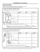
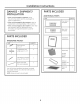
Installation Instructions PARTS INCLUDED DAMAGE- SHIPMENT/ INSTALLATION ADDITIONAL • If the unit is damaged in shipment, return the unit to the store in which it was bought for repair or replacement. PARTS m PART • If the unit is damaged by the customer, repair or replacement is the responsibility of the customer. QUANTITY TOPCABINETTEMPLATE • If the unit is damaged by the installer (if other than the customer), repair or replacement must be made by arrangement between customer and installer.
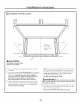
Installation Instructions TOOLS YOU WILL NEED Ruleror tape measure and # i and #2 Phillips screwdriver Tinsnips (for cutting damper, if required) Pencil Carpentersquare (optional) ht edge Scissors(to cut template, if necessary) Electric drill with VX', V_G", W' and s/8"drill bits 0 Gloves Saw(saber,hole or keyhole) Stud finder I ¢5b Filler blocksor scrap wood pieces,if needed for top cabinet spacing (usedon recessedbottom cabinet installations only) Hammer(optional) OF Safetygoggles Level
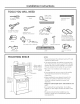
Instollotion -IPLACEMENT Instructions OF THE MOUNTING PLATE REMOVING THE OVEN FROM THE CARTON/REMOVING THE MOUNTING PLATE FINDING THE WALL STUDS % Remove the box containing the installation instructions, filters, exhaust adaptor, damper and the small hardware bag. Do not remove the foam packing protecting the front of the oven. [] Wall Studs Fold back all 4 carton flaps fully against carton sides. Then carefully roll the oven and carton over onto the top side.
Installation [_ DETERMINING Plate position cabinet Instructions WALL PLATE LOCATION UNDER YOUR CABINET - beneath Plate position - beneath cabinet bottom flat bottom framed recessed Mounting Plate Tabs Touching the Back Frame Mounting PlateTabs Touching the Cabinet :.Bottom o II "30" i At least 30", up to 36" Plate position - beneath recessed cabinet with front overhang to Cooktop ,, I bottom Your cabinets may have decorative trim that interferes with the oven installation.
Installation _ ALIGNING Instructions THE WALL PLATE Hole b---- Draw a Vertical Line on Wall from Center of Top Cabinet I olo I Hole C 4 TI Area E JI ACAUTION'. Wear gloves to avoid cutting fingers on sharp edges. [_ [_ [_ NOTE: Holes Cand D are inside area E.If neither C nor D is in a stud, find a stud somewhere in area E and draw a fifth circle to line up with the stud. It is important to use at least one wood screw mounted firmly in a stud to support the weight of the oven.
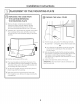
Installation 2-I INSTALLATION This oven is designed 3 types of ventilotion: for adaptation A. Outside Top Exhaust B. Outside Back Exhaust C. Recirculating TYPES Instructions {Choose A, B or C) NOTE: For JVM1950, PVM1970, DVM1950, and PVM2170 models. This oven is shipped assembled for Outside Top Exhaust. Select the type of ventilation required for your installation and proceed to that section.
Installation -IOUTSIDE INSTALLATION TOP EXHAUST Instructions {Vertical Duct) OVERVIEW A1. Attach Mounting Plate to Wall A2. Prepare Top Cabinet A3. Install Adaptor A4. Mount Oven AS. Adjust Exhaust Adaptor A6. Connect Ductwork _=_ ATTACH THE MOUNTING TO THE WALL To use toggle PLATE _-I_,-k_-- bolts: Spacing for Toggles Hare Than Wall Thickness Mounting i Toggle Wing_ Bolt End [_ Attach the plate to the wall using toggle bolts.
Installation Instructions USE TOP CABINET TEMPLATE FOR PREPARATION OF TOP CABINET _ MOUNT THE OVEN You need to drill holes for the top support screws, a hole large enough for the power cord to fit through, and a cutout large enough for the exhaust adaptor. CA UTI'0N:to t risk ,eofpersonal injury (back injury or other injuries due to excessive weight of the microwave) or property damage, you will need two people to install this microwave. IMPORTANT: Do not grip or use handle during installation.
Installation _ [_ Instructions ADJUST THE EXHAUST ADAPTOR MOUNT THE OVEN {continued) Open the top cabinet and adjust the exhaust adaptor to connect to the house duct. Attach the oven to the top cabinet. [_ Insert 2 self-aligning screws (¼"-28 x 2 sA')through outer top cabinet holes. Turn two full turns on each screw.
Installation r OUTSIDE BACK EXHAUST B2. INSTALLATION OVERVIEW to Wall B1. Attach PrepareMounting Rear WallPlate (Horizontal l B3. ivlount BS. Preparethe Top Oven Cabinet --- Duct} ! ! B4. Adjust Blower J-_ Instructions :_ _ ,_ U_L] __ _ ATTACH THE MOUNTING TO THE WALL PREPARING THE REAR WALL FOR OUTSIDE BACK EXHAUST PLATE You need to cut an opening in the rear wall for outside exhaust. :i ........... -_ iii/i j Attach the plate to the wall using toggle bolts.
Installation To use toggle Instructions bolts: [=_ Spacing for Toggles More -_l_-_----Than Wall Thickness Mounting ADAPTING BLOWER FOR OUTSIDE BACK EXHAUST [_ Remove the blower motor screw that holds the blower plate to the oven. Lift the front of the blower plate to install the blower. Toggle Wings Motor BlowerScrew'___ BlowerPlate Platemj_ _" Bolt End [_ Place the mounting plate against the wall and insert the toggle wings into the holes in the wall to mount the plate. ......
Installation I_ Instructions Roll the blower unit 90° so that fan blade openings are facing out the back of the oven. BeforeRolling I_ Attach the exhaust adaptor to the rear of the oven by sliding it into the guides at the top center of the back of the oven. After Rolling Exhaust Ad%tor Slide exhaust adaptor into guides on oven re%. Back of Oven Backof Oven % Locate the two "knockout" plates, on the rear oven panel, near the top of the oven. _.
Installation Instructions Cabinet Front F_ MOUNT THE OVEN Cabinet Bottom Shelf FillerBlock _This distance TEquivalent | can NOT I to Depth I of Cabinet |exceed 2" |to ensure ! | _ proper _installation _,CA UTI O .Toavoid theriskofpersonal -- injury (back injury or other injuries clue to excessive weight of the microwave) or property damage, you will need two people to install this microwave. OvenTop [_ Attach the oven to the top cabinet.
Installation [ RECIRCULATING INSTALLATION {Non-Vented Instructions Ductless) OVERVIEW C1. Attach Mounting Plate to Wall C2. Prepare Top Cabinet C3. Adjust Blower C4oMount the Oven I C5. Install Charcoal Filter (Supplied with JNM1951, DVM1950 and PNM1971 models) ATTACH THE MOUNTING TO TH E WALL [_ PLATE Place the mounting plate against the wall and insert the toggle wings into the holes in the wall to mount the plate.
Installation r_ Instructions ADAPTING BLOWER FOR RECIRCULATION [_ Place the blower unit back into the opening. _k WA RN !NG: Risk ofelectric shock NOTE:The exhaust adaptor with damper is not needed for recirculating models. You may want to save them for possible future use. can cause injury or death. Do not pull or stretch the blower unit wiring. Hake sure the wired are not pinched. [_ Carefully pull out the blower unit. The wires will extend far enough to allow you to adjust the blower unit.
Installation _4-1 MOUNT Instructions THE OVEN [_ Insert a self-aligning screw through top-center cabinet hole. Temporarily secure the oven by turning the screw at least two full turns after the threads have engaged. (It will be completely tightened later.) Cabinet Front Cabinet Bottom Shelf Filler Block TEquivaJent J to Depth [ of Cabinet .
Installation Instructions INSTALLING THE CHARCOAL FILTER [_ Remove 2 screws on top of oven, just above the grille panel, using a Phillips screwdriver. [_ [_ Open the door. Remove the grille. Slide the grille to the left then pull out. Screws [_ Insert the filter into the oven us shown until it fits squarely into place. It will rest at an angle behind the front lower tabs. When properly installed, the wire mesh of the filter should be visible from the front.
Installation Instructions BEFORE YOU USE YOUR OVEN Make sure the oven has been installed according to instructions. Remove all packing material from the oven. i m [_] Replace house fuse or turn breaker back on. 120 V Models: Plug power cord into a dedicated !5- to 20-amp electrical outlet. Ensure proper ground exists before use.
Printed in Korea 24
I strucci de i stal Horno microondas para iocar encima de ia estufa JVM7195,JNM7196, DVM7195,PVM9195, PNM9196y PVM9215 i ANTES DE EMPEZAR Lea estas instrucciones complet° y cuidadosamente. . Nota par° el consumidor - Guarde estas instrucciones para futura referencia. . IMPORTANTE - Guordeestos . Nivel de destrezas - LGinstaluci6n de este upuruto requiere de destrezas bc_sicasde mecc_nicay electricidad. instrucciones paro el uso clel inspector local. . IMPORTANTE - Cump,ocontodos,os.
Instrucdonesde instalaci6n [_ CONTENIDO Informaci6n Recirculaci6n ............................................................ 19-22 C6mo adherir la placa de montaje a la pared ............................................ 19 general Instrucciones de seguridad importantes ......................3 Preparaci6n del gabinete superior ............. 19 Requisitos el_ctricos ........................................................3 C6mo adaptar el soplador para la recirculaci6n ...............................
Instrucciones de instolaci6n NSTRUCCIONES DE SEGURIDAD IMPORTANTES Este producto requiere un tomacorriente el6ctrico de tres patas conectado a tierra. El instalador debe Ilevar a cabo una inspecci6n de continuidad a tierra en la caja el6ctrica antes de comenzar la instalaci6n para asegurar que la caja tomacorriente est6 conectada a tierra de manera apropiada.
Instrucciones de instalaci6n CAMPANA DE ESCAPE NOTA: Lea las siguientes dos p6ginas solamente si planea ventilar el escape hacio el exterior. Si por el contrario planea recircular el aire de vuelta hacia el sal6n, contin6e en la p6gina 30. ESCAPE SUPERIOR EXTERNO (EJEMPLO SOLAMENTE) La siguiente tabla describe un ejemplo de una posible instalaci6n de red de conductos.
Instrucciones de instalaci6n NOTA: Si usted necesita instalar conductos, tenga pendiente que la Iongitud total del conducto rectangular de 3¼" x 10" o el conducto redondo de 6" de di6metro no debe sobrepasar 140 pies equivalentes. Longitud Los codos, transiciones, paredes y tapas de techo, etc., presentan resistencia adicional al flujo de aire y son equivalentes a una secci6n de conducto recto el cual es m6s largo que su tamaho fisico real.
Instrucdonesde instalaci6n PARTES INCLUIDAS DANOS- ENVJO / INSTALACION J PARTES ADICIONALES • Si la unidad se daSa durante el envio, devuelva la unidad al almac6n clonde la adquiri6 para su reparaci6n o reemplazo. CANTIDAD PARTE • Si el cliente daSa la unidad, la reparaci6n o el reemplazo es responsabilidad clel cliente. TOP CABINETTEMPLATE • Si el instalador da5a la unidad (si no es el cliente), la reparaci6n o reemplazo se clebe hacer por meclio de un arreglo entre el cliente y el instalador.
Instrucciones de instalaci6n HERRAMIENTAS OUE NECESITARA _Z Destornilladoresde estrella # iy # 2 Tijeras para cortar lat6n (para cortar el regulador de tiro, si es necesario) .........
Instrucciones de instalaci6n C6MO COLOCAR EL PLATO DE MONTAJE [_] C6MO REMOVER EL HORNO DEL EMBALAJE / C6MO REMOVER EL PLATO DE MONTAJE IBI C6MO ENCONTRAR LOS POSTES DE VIGA EN LA PARED % Remueva lu cajo que contiene las instrucciones de instulaci6n, los filtros, el adaptador de escape, el regulador de tiro y la peque_a balsa con los elementos de instalaci6n. No remueva lu espuma de poliestireno que protege el frente del horno. [] Pastesde vig_ en la pared i Pliegue hacia atr6s las alas de la caja.
Instrucciones de instalaci6n C6MO DETERMINAR DE SU GABINETE Posici6n del plato de rondo piano - debajo LA LOCALIZACION DEL PLATO DE MONTAJE DEBAJO Posici6n del plato = debajo de gabinetes de rondo apoyado en un marco de gabinetes Las orejillas del plato de montaje tocan el fondo del gabinete Lasorejillasdel plato de montaje tocan el marco posterior o °oIo 30"' hasta la estufa Por to menos 30", hasta 36" Posici6n del plato de fondo apoyado - debajo de gabinetes con frente saliente Plato de montaje
Instrucciones de instalaci6n C6MO ALINEAR EL PLATO DE MONTAJE SOBRE LA PARED Trace una linea vertical en la pared a partir del _=--centro del gabinete superior Agujero .................. I Agujero C _Agujero B / I.................. O0OO0000100000000 000o0o00_00000o00 Agujero D ?........ T Area E JI PRECAUCION: Use guantesde protecci6n paraevitar cortadurasen sus dedos con losextremosfilosos. [] [_ [_ Trace una linea vertical en la pared en el centro del espacio de 30" de ancho.
Instrucciones de instalaci6n 2-JTIPOS DE INSTALACION (Escoja A, B o C) Este homo est6 disehado para adaptarse a los siguientes tres tipos de ventilaci6n: NOTE:Para modelos JVMI950, PVMI970, DVM1950, y PVM2170. Este homo es enviado ya ensamblado para un Escape Superior Exterior. Seleccione el tipo de ventilaci6n requerido para su instalaci6n y proceda a tal secci6n. A. Escape Superior Exterior (Conducto vertical) B. Escape Posterior Exterior (Conducto horizontal) C.
Instrucdonesde instalaci6n ESCAPESUPERIOR EXTERIOR (Conducto vertical) PERSPECTIVA GENERAL DE LA INSTALACION AI. Como adherir el plato de montaje a la pared A2. Prepare el gabinete superior A3. Instale el adaptador A4. Monte el homo A5. Ajuste el adaptador de escape A6. Conecte el conducto Para usar los tornillos COMO ADHERIR LA PLACA DE MONTAJE A LA PARED Af _ Plato de monta ]! ' Extremodel tornillo [_ Remueva las mariposas del basculante de los tornillos.
Instrucciones de instalaci6n _USE COMO MONTAR EL HORNO LA PLANTILLA DEL GABINETE SUPERIOR PARA LA PREPARACI6N DEL GABINETE SUPERIOR Deber6 perforer egujeros pera los tornillos de epoyo superiores, un egujero suficientemente grende pure que el cable el6ctrico quepe, yun recorte Io suficientemente grende como peru que el edeptedor de escape puede set introducido.
Instrucciones de instalaci6n J-ATJC6MO AJUSTAR EL ADAPTADOR COHO MONTAR EL HORNO DE ESCAPE (continuad6n} [_ Pegue el homo o Io porte superior del gubinete. [_ Abra el gabinete superior y ajuste el adaptador de escape para conectarlo al conducto de la casa. Inserte 2 tornillos (VJ'-28 x 2 sA") outoalineables a troves de los agujeros exteriores superiores del homo. Gire dos vueltos completos en coda tornillo.
Instrucciones de instalaci6n ESCAPE POSTERIOR E×TERNO (Cond ucto horizonta I) PERSPECTIVA GENERAL DE LA INSTALACI6N BIo Prepare la pared posterior B2. Pegue el plato de montaje a la pared B3. Prepare el gabinete superior B4, Ajuste el soplador B5.Monte el homo I I II IL C6HO ADHERIR EL PLATO C6HO PREPARAR LA PARED POSTERIOR PARA EL ESCAPE POSTERIOR EXTERIOR DE IONTAJE Necesita cortar una abertura en la pared posterior para el escape exterior. A LA PARED i ...........
Instrucciones de instalaci6n Para usar los tornillos basculantes: FB4] C6MO ADAPTAR EL SOPLADOR PARA EL ESCAPEPOSTERIOR EXTERIOR [_ Retire el tornillo del motor del soplador que sostiene el plato soplador sobre el homo. Levante la parte frontal del plato soplador para instalar el soplador. Tornillodel motor del soplador [_ Coloque el plato de montaje contra la pared e inserte las alas de mariposa en los agujeros de la pared para montar el plato. _____ _,s_ _< J--c-"_J\ .... _"___" .,_/ .
Instrucciones de instalaci6n I_ Ruede la unidad del soplador 900 de forma tal que las aberturas de la paleta del ventilador est6n orientadas hacia la parte posterior del homo. Antes de la Despu6sde la rotaci6n I_ Pegue el adaptador de escape a la parte posterior del horno desliz6ndolo en las gufas en la parte superior central de la parte posterior del horno.
Instrucciones de instalaci6n COHO MONTAR EL HORNO Frente del gabinete Estante del fondo del gabinete Bloque de relleno "TEquivalente a Esta distancia NO I laprdundidac puede superar las I del retsoceso rRC . U IUI :Ario deevitor eJ _del gabinete riesgo de lesi6n personal (lesi6n en la espalda u otras lesiones debido a peso excesivo del homo de microondas) o daffos sobre el producto, deber6 contar con la ayuda de dos personas para instalar este homo de microondas.
Instrucdonesde instalaci6n RECIRCULACION {sinconducto PERSPECTIVA GENERAL DE LA INSTALACI6N C1. Pegue el plato de montaje a la pared C2. Prepare el gabinete superior de ventilaci6n) W 11 ii __ ._. C3. A]uste el soplador C4. Monte el horno 6-- .............. :__r- C5.
Instrucciones de instalaci6n C6MO ADAPTAR EL SOPLADOR PARA LA RECIRCULACION [_ A NOTA: El adaptador de escape con soplador no es necesario para los modelos de recirculaci6n. Quizds desee guardarlos para posibles usos futuros. [] li_ Tornillo del y'Y .._" [_ _ [_ sop lador Cierre el plato soplador. Asegure el mismo con el tornillo retirado anteriormente. Plato soplador Cuidadosamente tire del soplador.
Instrucciones de instalaci6n _C-4] C6MO MONTAR EL HORNO (continuaci6n) COHO MONTAR EL HORNO [_ AI_PRir_(_AU L_IUN: Frente del gabinete Afin de evitar el Estante del fondo del gabinete riesgo de lesi6n personal (lesi6n en la espalda u otras lesiones debido a peso e×cesivo del homo de microondas) o da_os sobre el producto, deber6 contar con la ayuda de dos personas para instalar este horno de microondas, IMPORTANTE: No tome ni use la manUa durante instalaci6n. ADVERTENCIA: Inse.
Instrucciones de instalaci6n IC51 COMO INSTALAR EL FILTRO DE CARBONILLA [_ Remueva los 2 tornillos en la parte superior del homo, justo encima de la rejilla usando un destornillador de estrella. [_ Abra la puerta. [_ Remueva la rejilla. Deslice la rejilla hacia la izquierda y luego empuje hacia afuera. i__ T°rnill°s i Rejillo__ [_lnserte el filtro en horno como se muestra hasta que se ajuste correctamente en su lugar. Descansar6 en un 6ngulo detras de las orejillas inferiores frontales.
Instrucdonesde instalad6n ANTES DE COIVIENZARA USAR SU HORNO Cerci6rese de que el horno ha sido instalado de acuerdo con las instrucciones. r_ Manual de Usuario Instrucciones de Instalaci6n r_ ! Lea el Manual del Propietario. emueva del homo. todos los materiales de embalaje r_ UARDEESTASINSTRUCCIONES PARAEL USO DEL INSPECTORLOCAL. | Instrucciones Instale el aro rotatorio y con ruedas en la cavidad. 1 de Instalaci6n Reemplece el fusible de la casa o encienda de nuevo el interruptor.
Printed in Korea Impreso en Corea