THERMOSTAT Digital Non-Programmable OWNER’S MANUAL & INSTALLATION INSTRUCTIONS RAK148F2 RAK164F2 SAFETY INFORMATION .............................. 2 OVERVIEW............................................................... 3 INSTALLATION ............................................. 4–7 CONFIGURATION MODE ........................8, 9 OPERATING FUNCTIONS ....................... 10 TESTING THERMOSTAT ...................11–12 TROUBLESHOOTING ................................... 13 WARRANTY ....................
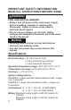
IMPORTANT SAFETY INFORMATION READ ALL INSTRUCTIONS BEFORE USING WARNING FIRE AND SHOCK HAZARD • Always turn off power at the main power supply before installing, cleaning or removing the thermostat. Failure to do so could result in electrical shock hazard. • Do not use on voltages over 30 VAC. Higher voltages will damage the thermostat and could cause shock or fire hazard. NOTICE • All wiring must conform to local and national electrical and building codes.
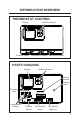
INTRODUCTION OVERVIEW THERMOSTAT CONTROL Display Up/Down Buttons Cool Off Heat Function Switch Auto On Low High Fan Auto/On Switch Fan Speed Switch PARTS DIAGRAM Up/Down Buttons Display Wiring Channel Mounting Hole Mounting Hole LEFT RIGHT COOL Configuration Buttons RESET OFF B GH GL Y W C R HEAT Function Switch AUTO ON Fan Auto/On Switch LOW HIGH Fan Speed High/Low 3
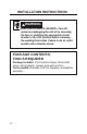
INSTALLATION INSTRUCTIONS WARNING ELECTRICAL SHOCK HAZARD—Turn off power by unplugging the unit or by removing the fuse or switching the appropriate circuit breaker to the OFF position before removing the existing thermostat. Failure to do so could result in risk of electric shock. PACKAGE CONTENTS/ TOOLS REQUIRED Package includes: Thermostat on base, thermostat cover, wiring labels, screws and wall anchors. Tools needed: 'ULOO ZLWK Ǝ ELW KDPPHU VFUHZGULYHU and putty.
INSTALLATION INSTRUCTIONS TO REMOVE EXISTING THERMOSTAT 1. Turn off power to heating and cooling system by removing the fuse or switching off the appropriate circuit breaker. 2. Remove cover of old thermostat. This should expose the wires. 3. Label the existing wires with the enclosed wire labels before removing wires. 4. After labeling wires, remove wires from wire terminals. 5. Remove existing thermostat base from wall. 6. Refer to the following section for instructions on how to install this thermostat.
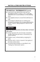
INSTALLATION INSTRUCTIONS TO INSTALL THERMOSTAT IMPORTANT: Thermostat installation must conform to local and national building and electrical codes and ordinances. Note: Mount the thermostat about five feet above the floor. Do not mount the thermostat on an outside wall, in direct sunlight, behind a door or in an area affected by a vent or duct. 1. Turn off power to the heating and cooling system by removing the fuse or switching off the appropriate circuit breaker. 2.
INSTALLATION INSTRUCTIONS TO INSTALL THERMOSTAT (cont.) 10. Seal hole for wires behind thermostat with nonflammable insulation or putty, or use a wall plate obtainable from a local hardware or home building store. 11. Use supplied screws to mount thermostat base to wall. 12. Insert stripped, labeled wires in matching wire terminals by pressing on the corresponding terminal contact. See the “Wiring Diagrams” section of this manual. NOTICE Make sure exposed portion of wires does not touch other wires. 13.
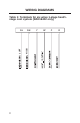
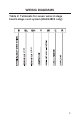
WIRING DIAGRAMS Table 1: Terminals for six wires 1-stage heat/1stage cool system (RAK164F2 only) 8 GH -HIGH -LOW GL Y W C R
WIRING DIAGRAMS Table 2: Terminals for seven wires 2-stage heat/1-stage cool system (RAK148F2 only) GH Y W C R -HIGH GL -LOW B 9
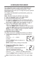
CONFIGURATION MODE > > < < The configuration mode is used to set the RAK148F2 and RAK164F2 to match the heating/cooling system. These thermostats function with up to 2-stage heat pump systems (RAK148F2 only). To configure the RAK148F2 and RAK164F2, perform the following steps: Note: Operation being set will blink in the display. 1. Slide the Function switch to the OFF position. 2. Remove the thermostat’s front cover. 3.
> > > > < < < < 3. Temperature Differential—Stage 2 (1–9°F/1–5°C) RAK148F2 only Set the number of degrees between when stage 1 turns on and stage 2 turns on. Press the or button to set differential value. Press the RIGHT button to advance to the next screen. Note: Default factory setting is 2°F/1°C for each stage. 4. Minimum Cool Setpoint (60, 64, 66, 68, 70, 72, 74, 76°F) (15, 17, 19, 20, 21, 22, 23, 24°C) Adjust to control the minimum Cool set temperature allowed. Press the or button to select.
OPERATING FUNCTIONS Off • In this mode, the thermostat will not turn on the heating or cooling devices (manual fan can operate). • Off is also used to access Configuration mode. > < Cool • In this mode, the thermostat controls the cooling system. • Press the or button to set the desired temperature. 12 > < Heat • In this mode, the thermostat controls the heating system. • Press the or button to set the desired temperature.
TESTING THE THERMOSTAT Once the thermostat is installed, it should be thoroughly tested. NOTICE Do not use air conditioning beyond the simple test when the outdoor temperature is below 50 degrees. This can damage the air conditioning system. Note: Before testing the thermostat, move the Fan Auto/On switch to the Auto position. Fan Test 1. With Function switch set to Off, slide Fan Speed switch to High, and slide Fan Auto/On switch to On position. 2. Indoor fan turns on in high speed. 3.
TESTING THE THERMOSTAT Heat Test 1. Slide Function switch to Heat position. Heat mode screen is displayed. 2. Adjust set temperature so it is 5 degrees above room temperature. 3. Heat should come on within a few seconds. 4. Adjust the set temperature so it is 2 degrees below the room temperature and the heat should turn off. Note: There is a 3 minute time delay and a 3 minute minimum run time for the compressor when it turns on/off. (On some models, the fan may also have a minimum run time/ off time delay).
TROUBLESHOOTING TIPS Problem Solution No Display Check for 24 VAC; display is blank when 24 VAC is not present System fan does not come on properly Verify that wiring is correct. All thermostat buttons are inoperative Verify that 24 VAC is present; unit will not operate when 24 VAC is not present. Thermostat turns on and off too frequently Adjust temperature differential VHH &RQ¿JXUDWLRQ 0RGH 6HWWLQJ Temperature Differential, Stage 1 and Stage 2 section).
THERMOSTAT WARRANTY Staple your receipt here. Proof of the original purchase date is needed to validate the warranty. For The Period Of: GE Appliances Will Replace: One Year From the date of the original purchase Full Replacement of the thermostat which fails due to a defect in materials or workmanship. What GE Appliances Will Not Cover: Ŷ Service trips to your location. Ŷ Improper installation. If you have an installation problem, contact your installer.