
Installation Guide

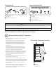


Select Installation Position
2
Canopy
Undershelf
Nose
• Select installation position:
2A Undershelf
2B Canopy and Nose
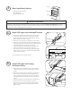
• Remove each shelf and turn upside down on work surface.
• Thread LED Light wire through the large hole in selected
mounting clip and slide over the end of LED Light. Slightly
tighten thumb screw. Refer to Figure 1.
• Slide second mounting clip over opposite end of LED Light.
• With mounting clips still attached, place LED Light ush with
shelf edges, positioning it as far forward as possible while still
concealing LED Light from view. Refer to Figure 2.
• Install mounting clip to shelf with two #6 self-drilling pan
headed screws per mounting clip. Refer to Figure 3.
• Insert tension screw into both mounting clips and partially
tighten each screw into nut to enable the LED Light position
to adjust. Refer to Figure 4.
Install LED Lights into Undershelf Position
Shelf installation shown in gures at right.
3A
Figure 1
Figure 2
Install LED Lights into Canopy
and Nose Position
Attach mounting clip
Shelf
Position forward
Install mounting clip
Tighten thumb screw
Figure 4
Figure 3
• Thread LED Light wire through the large hole in selected
mounting clip and slide over the end of LED Light. Refer to
Figure 1.
• Slide second mounting clip over opposite end of LED Light.
• With mounting clips still attached, place LED Light ush
against mounting surface, positioning it as far forward as
possible while still concealing LED Light from view. Refer to
Figure 2.
• Install mounting clips to panel with two #6 self-drilling pan
headed screws per mounting clip. Refer to Figure 3.
• Insert thumb screw into one mounting clip and partially
tighten screw to enable the LED Light position to adjust.
Refer to Figure 4.
3B
WARNING/AVERTISSEMENT
Risk of electrical shock. Only those open holes indicated in the photographs and/or drawings may be made or altered as a result of kit
installation. Do not leave any other open holes in an enclosure of wiring or electric components / Risque de choc électrique. Seuls les trous
ouverts indiqués dans les photos et / ou les dessins peuvent être faites ou modiés à la suite du montage du kit. Ne pas laisser autres trous
ouverts dans l'enceinte du câblage électrique ou composants.