
Specification Sheet


S-5582.B rev.0708
BASIC DRY VACUUM PUMP DESCRIPTION
ROOTS™ DVJ WHISPAIR™ dry exhausters have an
exclusive discharge jet plenum design which allows
cool, atmospheric air to flow into the cylinder. This
unique design permits continuous operation at
vacuum levels to blank-off with a single stage unit.
Standard dry exhausters are limited to approx.
16” Hg vacuum because operation at higher vacuum
levels can cause extreme discharge temperatures
resulting in casing & impeller distortion and possible
seizure. The DVJ vacuum exhauster’s integral cooling
design eliminates the problems associated with high
temperatures at vacuum levels beyond 16” Hg.
DVJ WHISPAIR™ exhausters are heavy-duty units
with integral-shaft ductile iron impellers. The casing,
headplates, gear cover and drive end cover are grey
iron. Carburized and ground alloy steel spur timing
gears are taper mounted on the shafts, secured with a
locknut. Cylindrical roller bearings are splash lubricated
at both the gear end and drive end. Piston rings reduce
air leakage through the headplate bores and lip-type oil
seals prevent lubricants from entering the air chamber.
Rugged steel mounting feet permit infield adaptability
to either vertical or horizontal installation requirements.
ROOTS™ DVJ WHISPAIR™ exhausters can be
arranged to operate in two and three stage systems
to achieve vacuum levels down to 1 Torr.
WARRANTY PERIOD
Twelve (12) months from date of original unit
start-up or 18 months from date of original
shipment, whichever occurs first.
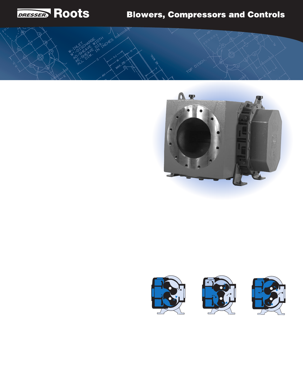
OPERATING PRINCIPLE
DESIGN AND CONSTRUCTION FEATURES
1. Rigid cast iron cylinder and headplates
2. Anti-friction cylindrical roller bearings
3. Splash lubricated spur timing gears
4. Inlet and discharge connections in standard
pipe sizes
5. Involute profile ductile iron impellers
POSITION 3
POSITION 2POSITION 1
Position 1: Incoming air is trapped between the impellers. Simultaneously,
pressurized air is being discharged. Position 2: As the upper impeller passes
the jet plenum, cooled, pressurized air flows into the space between the
impeller and cylinder. This cools the trapped air, helps control thermal growth
and allows higher discharge pressures. Position 3: The trapped air is then
moved into the discharge flange (left). Backflow is reduced, resulting in lower
operating noise level and reduced shock loading on the impellers.
SPECIFICATIONS
ROOTS
™
DVJ WHISPAIR
™
Dry Vacuum Exhausters
Frame 721J