GE Energy Roots* Centrifugal Compressors GE continues a history of innovation and technical leadership
GE Energy is a global leader in the design and manufacture of air and gas handling solutions. GE leverages its history of technical innovation to address key environmental issues and to provide current best practices in manufacturing to delivery of its products to customers around the globe. Here you will find an overview of the engineering quality and manufacturing expertise that comprises Roots centrifugal compressors.
Roots centrifugal compressors deliver high Multi-Stage Rotor Assembly IMPELLERS: Offered in many different designs and constructions of several different materials, depending upon the operating conditions and gas being handled. The impeller is statically and dynamically balanced and then oversped to 15% above maximum operating speed. The impeller is then mounted on the shaft with a suitable locking device and the rotor assembly is dynamically balanced.
performance and low maintenance. Standard Labyrinth Buffered Labyrinth Buffered Carbon Ring Double Opposed Dry Gas Seal w/ Buffer SEALS: Air applications use the Standard Labyrinth Seal, while Double Labyrinth, Carbon Ring and Dry Mechanical Seals are used for gas applications. Buffer and suction ports can be provided for additional retention of the process gas. Gas-tight shutoff sealing is also available to ensure gas retention when the compressor is not operating.
Roots IGCH Compressor Integrally Geared Dual Vane Characteristic Value 3 6 Flow, SCFM (Nm /hr) 4,000 to 42,000 (6,280 to 65,980) Polytrophic Head, ft*lbf/lbm (kJ/kg) 10,000 to 40,000 (29.9 to 119.
Roots IGCH Compressor Performance Map CAPACITY - Nm3/hr (1.013 bar(a), 0° C, 0% RH) 0 7854 15709 23563 31417 39272 47126 54980 62834 70689 78543 20 1.38 19 400 Frame Frame Frame Frame 12 16 20 24 30 1.31 1.24 300 HP ( 17 1.17 kW) 34 16 00 1.10 HP (25 35 13 HP 0.97 (22 40 0H 80 220 0H 0.83 (19 kW ) W 0 HP 7 1400 HP (1 0.69 640 kW ) 5 1000 4 10000 15000 20000 25000 CAPACITY - SCFM (14.7 PSIA, 68° 30000 0.62 0.55 (134 0 kW ) 0.
Name 8 Description Compressor/Gear Box Assembly incorporating a centrifugal compressor (rotor assembly, inlet housing, volute, casing cover, and bearing stand) and a speed increasing gear box in one housing. The compressor design is capable of facilitating the use of both inlet guide vanes as well as diffuser vanes (variable or fixed) for optimal efficiency over a wide range of performance points. Capable of meeting API672 and API-617.
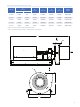
Roots IGCH Compressor Dimension Table A* B* C D E Weight inches (mm) inches (mm) inches (mm) inches (mm) lbs (kgs) inches (mm) Unit Size MIGV’S** MPGV’S** 12" IGCH 12 (300) N/A 12 (300) 170 (4300) 84 (2130) 65 (1650) 20,000 (9,070) 16" IGCH 16 (400) 20 (500) 16 (400) 185 (4700) 84 (2130) 70 (1780) 26,000 (11,800) 20" IGCH 20 (500) 24 (600) 20 (500) 200 (5080) 84 (2130) 73 (1850) 33,500 (15,200) 24" IGCH 24 (600) 30 (750) 24 (600) 220 (5600) 84 (2130) 84 (2130) 42
Roots OIB Compressor Characteristic Value 3 Flow, SCFM (Nm /hr) 5,000 to 225,000 (7,850 to 353,440) Polytrophic Head, ft*lbf/lbm (kJ/kg) 10,000 to 40,000 (29.9 to 119.
Roots OIB Compressor Map CAPACITY - Nm3/hr (1.013 bar (a), 0°C, 0% RH) 0 78543 235629 157086 392715 314172 1.38 20 100 45 50 75 35 200 150 260 1.
Name 12 Description Compressor Overhung style centrifugal compressor consisting of a rotor assembly, inlet housing, volute, casing cover, and bearing stand. Optional inlet guide vanes allow for process control in the absence of a variable speed drive or inlet throttling valve. Capable of meeting API-617. Gear Box Speed increasing gear box designed to increase the driver input speed up to the rated compressor speed.
Roots OIB Compressor Dimension Table Unit Size OIB-35 A* inches (mm) W/ IGV’S W/O IGV’S 16 (400) 16 (400) B* inches (mm) C inches (mm) D inches (mm) E inches (mm) Weight lbs (kgs) 16 (400) 200 (5080) 72 (1830) 78 (1980) 30,000 (13,600) OIB-45 20 (500) 20 (500) 20 (500) 210 (5330) 84 (2130) 78 (1980) 40,000 (18,150 OIB-50 18 (450) 20 (500) 16 (400) 220 (5600) 96 (2440) 78 (1980 40,000 (18,150) OIB-75 24 (600) 22 (550) 18 (450) 220 (5600) 114 (2900) 81 (2060) 42,000 (19,
Roots Type H Horizontally-Split Multi-Stage Compressor Characteristic Value 3 14 Flow, SCFM (Nm /hr) 6,000 to 67,000 (9,430 to 105,250) Polytrophic Head, ft*lbf/lbm (kJ/kg) 14,000 to 65,000 (41.8 to 194.3) Casing Materials Cast iron, ductile iron (special materials available upon request) Impeller Materials Carbon steel, stainless steel Impeller Construction Semi-backward leaning and backward leaning blades (closed); welded or milled & welded Spec.
Roots H-Multi Stage Compressor Map CAPACITY - Nm3/hr (1.013 bar (a), 0°C, 0% RH) 0 15709 31417 47126 62834 78543 94252 109960 125669 75 5.17 ) kW 730 ) P (3 kW 0H 355 500 P (3 0H ) 450 5 kW (298 0 HP 400 kW) 610 HP (2 3500 W) 240 k HP (2 3000 kW) 865 HP (1 2500 ) 0 kW (149 0 HP W) 200 120 k HP (1 W) 1500 30 k W) HP (9 50 k 1250 HP (7 4 STAGE 1000 55 12 00 100 00 60 k W) HR-42 HT-48 W) 75 k HP (3 ) 500 0 kW P (19 250 H HQ-35 HP 89 50 00 60 kW ) (82 (74 3.
Name 16 Description Compressor Horizontally split centrifugal compressor consisting of top and bottom casing halves, rotor assembly, inter-stage diaphragms, seals, and bearing stands. Inlet section is capable of housing fixed or variable guide vanes for flow conditioning/ process control. Adaptable for up or down inlet and discharge connection orientations. Capable of meeting API-617. Driver Primary drive options are electric motors, with or without variable frequency drive, and steam turbines.
Roots Type H Multi-Stage Dimensional Table A* B* C** D E inches (mm) inches (mm) inches (mm) inches (mm) inches (mm) HN 18 (450) 14 (350) 192 (4880) 72 (1830) 78 (1980) 35,000 (15,875) HP 30 (750) 24 (600) 220 (5600) 102 (2590) 98 (2490) 71,500 (32,430) HQ 36 (900) 24 (600) 240 (6100) 108 (2740) 120 (3050) 78,000 (35,380) HR 42 (1050) 24 (600) 250 (6350) 120 (3050) 132 (3350) 92,000 (41,730) HT 48 (1200) 36 (900) 260 (6600) 138 (3500) 150 (3810) 130,000 (58,970)
Control solutions specific to your application Every Roots centrifugal compressor is designed to meet specific application requirements. To accomplish this we design control solutions to monitor the health of the compressor and its operation. We accomplish this with sophisticated instrumentation and high tech controls that provide conditional monitoring for such diverse systems as the compressor, lube oil systems, and an array of drive options.
Manufacturing Expertise The manufacturing methods and procedures at our 200,000 sq. ft. facility rely collectively on our highly skilled individuals and versatile machining.
GE Energy Houston, Texas USA Headquarters • U.S. Toll Free Phone: 1 877-363-ROOT(S) (7668) • Direct Phone: +1 832-590-2600 Connersville, Indiana USA Operations • U.S.