
Brochure


16
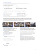
Name Description
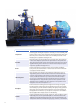
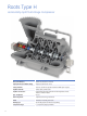
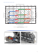
Compressor
Horizontally split centrifugal compressor consisting of top and bottom casing
halves, rotor assembly, inter-stage diaphragms, seals, and bearing stands.
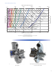
Inlet section is capable of housing fi xed or variable guide vanes for fl ow
conditioning/ process control. Adaptable for up or down inlet and discharge
connection orientations. Capable of meeting API-617.
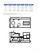
Driver
Primary drive options are electric motors, with or without variable frequency
drive, and steam turbines. In select instances internal combustion (IC)
engines have been utilized. A separate speed increasing gear box can be
included if needed for performance.
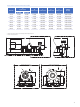
Lube Oil System
There are three main options for the compressor lube system. First, an
integral lube system; in which the lube oil reservoir is housed within the
structure of the baseplate, with the lube oil components (pumps, valves,
coolers, and fi lters) mounted on top of the reservoir with the compressor.
Second, a console lube system, with separate reservoir, mounted to the
baseplate frame. Lastly, the lube system can be a separate console shipped
loose for installation near the compressor. Lube systems can be designed to
meet API-614 Chapters 2 or 3.
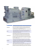
Baseplate
Boxed construction utilizing structural supports for bracing and rigidity.
Grouting pockets, anchor bolt holes and leveling screws are incorporated
into the design to provide additional stability and rigidity during operation.
Lifting lugs are incorporated into the design for ease in transportation of the
equipment from the factory to the job site. Compressors can additionally be
supplied with a drip lip and/or non-skid decking.
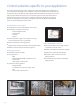
Controls
Provide conditional monitoring for the compressor, driver and lube oil system.
Additionally,the local control panel (baseplate or off mounted) houses the
intelligence for positioning inlet guide vanes. The local instrumentation and
panel provide real-time, local data through gauges, switches, or transmitters.