
Installation Instructions
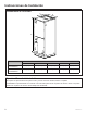
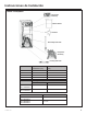
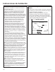
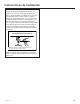
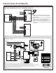
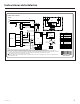
Table Of Contents

31-5000486 Rev. 2 17
Instrucciones de Instalación
AP1
Power
Indoor Unit - 4/5 ton
L1
L2
1
XT3
TC
RD
BK
BU
YE
WH
1
X1
2 3 4 5 6
G
W1
W2
G
CN1
W7 W8
W9
W10
W11
Thermostat
W13
X1 X2
X10
X4
X3
X9 X13 X7
Y
B
W1
R
C
G
Y
XT2
C
Y
G G
Y
C
B B B
W1 W1 W1
R R R
C
W5
W6
W3
W4
N 2
1
XT1
1
W14
X1
G
CB1 CB2
CB2
CB1
L1
L2
G
15KW Heat kit
Heat
Code Name
CB1
Circuit breaker only for
10KW heat kit
CB2
Circuit breaker only for
5KW heat kit
TC Transformer
XT1~XT3 Wiring board
Y
B
4-way valve control
signal, energized under
the heating mode
W1 Heater control signal
R 24V AC power supply
C 24V common
G Indoor unit fan signal
G
Fan
motor
M
XT1-1
XT1-2
YEGN
BK
RD
AP2
COM2
W12
①
DC_MOTOR1
4
4
Note:
1. Please refer to the instruction manual to check whether the unit can connect to the engineering electric heating.
2. When the unit doesn’t connect to the engineering electric heating, connect the engineering power supply to the W5(BK) and W6(WH) of X1.
3. When the unit connects to the engineering electric heating, connect the engineering power supply to the breaker.
4. The primary input voltage of transformer is defaulted at 230V(BK). When switching the power supply of the complete unit to 208V, connect the
primary input voltage of transformer to 208V(BU), which can be realized by exchanging the black wire and the blue wire.
5. 1 Only applicable for the unit whose motor is with earthing wire.
6. As for wiring, please refer to the parameters before “ /” of MCA and MOP of heat kit on the nameplate for CB1; please refer to parameters after “ /”
of MCA and MOP for CB2.