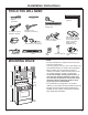
Installation Over the Range Instructions Microwave Oven BEFORE YOU BEGIN Read these instructions completely and carefully. • IMPORTANT – Save these • IMPORTANT – Observe all instructions for local inspector’s use. governing codes and ordinances. • Note to Installer – Be sure to leave these instructions with the Consumer. • Note to Consumer – Keep these instructions for future reference. • Skill level – Installation of this appliance requires basic mechanical and electrical skills.
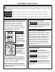
Installation Instructions This is the safety alert symbol. This symbol alerts you to potential hazards that can kill or hurt you and others. All safety messages will follow the safety alert symbol and the word “DANGER”, “WARNING”, or “CAUTION”. These words are defined as: DANGER Indicates a hazardous situation which, if not avoided, will result in death or serious injury. WARNING Indicates a hazardous situation which, if not avoided, could result in death or serious injury.
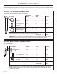
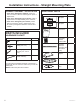
Installation Instructions HOOD EXHAUST NOTE: Read these next two pages only if you plan to vent your exhaust to the outside. If you plan to recirculate the air back into the room, proceed to page 11. OUTSIDE TOP EXHAUST (EXAMPLE ONLY) The following chart describes an example of one possible ductwork installation. EQUIVALENT NUMBER LENGTH x USED = LENGTH DUCT PIECES Roof Cap 24 Ft. x (1) = 24 Ft. 12 Ft. x (1) = 12 Ft. 12 Ft.
Installation Instructions NOTE: If you need to install ducts, note that the total duct length of 31⁄4″ x 10″ rectangular or 6″ diameter round duct should not exceed 140 equivalent feet. Outside ventilation requires a HOOD EXHAUST DUCT. Read the following carefully. NOTE: It is important that venting be installed using the most direct route and with as few elbows as possible. This ensures clear venting of exhaust and helps prevent blockages.
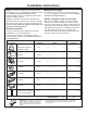
Installation Instructions TOOLS YOU WILL NEED Pencil #1 and #2 Phillips screwdriver Carpenter square (optional) Ruler or tape measure and straight edge Scissors (to cut template, if necessary) Tin snips (for cutting damper, if required) Electric drill with 3⁄16″, 7⁄16″, 1⁄2″ and 5⁄8″ drill bits Saw (saber, hole or keyhole) Gloves Level Safety goggles MOUNTING SPACE * 13-3/4″ max. 10-1/4” 30″ 66″ min. 31-7000188 Rev. 0 30″ min.
Installation Instructions - Straight Mounting Plate DAMAGE–SHIPMENT / INSTALLATION • I f the unit is damaged in shipment, return the unit to the store in which it was bought for repair or replacement. • If the unit is damaged by the customer, repair or replacement is the responsibility of the customer. • If the unit is damaged by the installer (if other than the customer), repair or replacement must be made by arrangement between customer and installer.
Installation Instructions 1. PLACEMENT OF THE MOUNTING PLATE A. R EMOVING THE MICROWAVE OVEN FROM THE CARTON A. R EMOVING THE MICROWAVE OVEN FROM THE CARTON 1. R emove the Installation Instructions, exhaust adapter, turntable ring, filters, glass tray, and the small hardware bag. Do not remove the foam protecting the top of the oven. NOTE: Do Not Remove the plastic plug protective cover until just before hanging the oven.
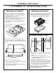
Installation Instructions 1. PLACEMENT OF THE MOUNTING PLATE C. DETERMINING MOUNTING PLATE LOCATION UNDER YOUR CABINET Plate Position – beneath flat bottom cabinet Plate Position – beneath framed recessed cabinet bottom 10-1/4” 30” to Cooktop Draw a vertical line on the wall at the center of the 30” wide space. Tape the Rear Wall Template onto the wall matching the centerline and touching the bottom of the cabinet.
Installation Instructions 1. PLACEMENT OF THE MOUNTING PLATE D. MARKING THE MOUNTING HOLES 3/8" TO EDGE 12" NOTE: IT IS VERY IMPORTANT TO READ AND FOLLOW THE DIRECTIONS IN THE INSTALLATION INSTRUCTIONS BEFORE PROCEEDING WITH THIS REAR WALL TEMPLATE. This Rear Wall Template serves to position the bottom mounting plate and to locate the horizontal exhaust outlet. 1. Use a level to check that the template is positioned accurately. 2.
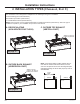
Installation Instructions 2. INSTALLATION TYPES (Choose A, B or C) This microwave oven is designed for adaptation to the following three types of ventilation: A. Recirculating (Non-Vented Ductless) B. Outside Top Exhaust (Vertical Duct) C. Outside Back Exhaust (Horizontal Duct) NOTE: This microwave oven is shipped assembled for Outside Top Exhaust (Vertical Duct). Select the type of ventilation required for your installation and proceed to that section. A. R ECIRCULATING (NON-VENTED DUCTLESS) C.
Installation Instructions 2. INSTALLATION TYPES (Choose A, B or C) A. R ECIRCULATING (Non-Vented Ductless) INSTALLATION OVERVIEW A1. A2. A3. A4. A5. Attach Mounting Plate to Wall Prepare Top Cabinet Check Blower Plate Mount the Oven Installing The Charcoal Filter OR T ANT T O NOT E : IT IS V E R Y I MP T HE DIR E CT IONS RE AD AN D F O LLOW INS T R UC T IONS IN T HE INS T ALLAT ION W IT H T HIS B E F OR E P R OCE E DING E. RE AR W ALL T E MP LAT ition the bottom 3/8" TO E DGE a long the dotted line.
Installation Instructions 2. INSTALLATION TYPES (Choose A, B or C) A3. C HECK BLOWER PLATE Blower Plate Cover Plate A4. MOUNT THE OVEN (cont) NOTE: When mounting the oven, thread power cord through hole in bottom of top cabinet. Keep it tight throughout Steps 1–3. Do not pinch cord or lift oven by pulling cord. 1. Lift oven, tilt it forward and hook slots at back bottom edge onto two lower tabs of mounting plate. •P lace the microwave in its upright position, with the top of the microwave facing up.
Installation Instructions 2. INSTALLATION TYPES (Choose A, B or C) A4. MOUNT THE OVEN (cont) 4. T ighten the two screws to the top of the oven completely. (While tightening screws, hold the oven in place against the wall and the top cabinet.) 5. I nstall grease filters. See the Owner’s Manual packed with the oven. 3. Change the charcoal filter from the vent plate. Charcoal Filter Vent Plate 4.
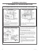
Installation Instructions 2. INSTALLATION TYPES (Choose A, B or C) B. O UTSIDE TOP EXHAUST (Vertical Duct) INSTALLATION OVERVIEW B1. Attach Mounting Plate to Wall B2. Prepare Top Cabinet B3. A dapting Microwave Air Director for Outside Top Exhaust B4. Check Damper Operation B5. Mount Microwave Oven B6. Adjust Exhaust Adaptor B7. Connecting Ductwork TO NOTE: IT IS VERY IMPORTANT THE DIRECTIONS READ AND FOLLOW INSTRUCTIONS IN THE INSTALLATION WITH THIS BEFORE PROCEEDING WALL TEMPLATE.
Installation Instructions 2. INSTALLATION TYPES (Choose A, B or C) B2. U SE TOP CABINET TEMPLATE FOR PREPARATION OF TOP CABINET You need to drill holes for the top support screws, a hole large enough for the power cord to fit through, and a cutout large enough for the exhaust adaptor. 2. Carefully pull out the AIR DIRECTOR. Before: Openings Facing Forward Air Director 3. Rotate the air director counterclockwise 180°.
Installation Instructions 2. INSTALLATION TYPES (Choose A, B or C) B3. ADAPTING MICROWAVE AIR DIRECTOR FOR OUTSIDE TOP EXHAUST (cont) B5. MOUNT THE OVEN 6. Attach the exhaust adaptor to the top of the blower plate by sliding it into the guides of the blower plate. Adaptor Guide Back of Microwave Locking Tab 7. P ush in securely until it is in the locking tabs. Take care to ensure that the damper hinge is installed so that the damper swings freely. B4.
Installation Instructions 2. INSTALLATION TYPES (Choose A, B or C) B5. MOUNT THE OVEN (cont) B6. ADJUST THE EXHAUST ADAPTOR Open the top cabinet and adjust the exhaust adaptor to connect to the house duct. Cabinet Front Cabinet Bottom Shelf Filler Block Blower Plate Back of Microwave Damper Equivalent to Depth of Cabinet Recess Self-Aligning Screw Oven Top 3. Attach the oven to the top cabinet by inserting 2 self-aligning screws through outer top cabinet holes. Turn two full turns on each screw.
Installation Instructions 2. INSTALLATION TYPES (Choose A, B or C) C. OUTSIDE BACK EXHAUST (Horizontal Duct) INSTALLATION OVERVIEW C1. Prepare Rear Wall C2. Attach Mounting Plate to Wall C3. Prepare Top Cabinet C4. Remove Blower Plate C5. A dapting Microwave Air Director for Outside Back Exhaust C6. Mount Microwave Oven C1. P REPARING THE REAR WALL FOR OUTSIDE BACK EXHAUST OPTION 2 3/8" TO EDGE STEP 1: Installer uses bracket to make 2 marks.
Installation Instructions 2. INSTALLATION TYPES (Choose A, B or C) C3. U SE TOP CABINET TEMPLATE FOR PREPARATION OF TOP CABINET C5. ADAPTING MICROWAVE AIR DIRECTOR FOR OUTSIDE BACK EXHAUST You need to drill holes for the top support screws and a hole large enough for the power cord to fit through. 1. Carefully pull out the AIR DIRECTOR. Before: Openings Facing Forward Air Director B D 2. Rotate the air director counterclockwise 180°.
Installation Instructions 2. INSTALLATION TYPES (Choose A, B or C) C5. ADAPTING MICROWAVE AIR DIRECTOR FOR OUTSIDE BACK EXHAUST C6. MOUNT THE OVEN 4. Place the air director back into the opening. After: Air Director Openings Facing Back FOR EASIER INSTALLATION AND PERSONAL SAFETY, WE RECOMMEND THAT TWO PEOPLE INSTALL THIS OVEN. 5. S ecure the blower plate to the microwave with the original screw. Blower Plate Cover Plate IMPORTANT: Do not grip or use the handle or heat shield during installation.
Installation Instructions 2. INSTALLATION TYPES (Choose A, B or C) C6. MOUNT THE OVEN (cont) Cabinet Front Cabinet Bottom Shelf Filler Block Equivalent to Depth of Cabinet Recess Self-Aligning Screw Oven Top 3. Attach the oven to the top cabinet by inserting 2 self-aligning screws through outer top cabinet holes. Turn two full turns on each screw. Be sure to keep power cord tight. Be careful not to pinch the cord, especially when mounting flush to bottom of cabinet. 4.
Installation Instructions BEFORE YOU USE YOUR MICROWAVE 1. M ake sure the microwave oven has been installed according to instructions. 6. Read the Owner’s Manual. 7. K EEP INSTALLATION INSTRUCTIONS FOR THE LOCAL INSPECTOR’S USE. 2. R emove all packing material from the microwave oven. 3. Install turntable and ring in cavity. 4. Replace house fuse or turn breaker back on. 5. P lug power cord into a dedicated 15- to 20-amp electrical outlet.
Instrucciones de instalación ANTES DE EMPEZAR Lea estas instrucciones completa y cuidadosamente. • • IMPORTANTE – Guarde estas instrucciones para el uso del inspector local. IMPORTANTE – Cumpla con todos los códigos y ordenanzas gubernamentales. • Nota para el instalador – Asegúrese de dejar estas instrucciones con el consumidor. Horno microondas para colocar encima de la estufa Nota para el consumidor – Guarde estas instrucciones para futura referencia.
Instrucciones de Instalación INSTRUCCIONES DE SEGURIDAD IMPORTANTES Éste es el símbolo de alerta de seguridad. El mismo alerta sobre potenciales riesgos que le pueden producir la muerte o lesiones tanto a usted como a otras personas. Todos los mensajes de seguridad estarán a continuación del símbolo de alerta de seguridad y con la palabra “PELIGRO”, “ADVERTENCIA” o “PRECAUCIÓN”.
Instrucciones de Instalación CAMPANA DE ESCAPE NOTA: Lea las siguientes dos páginas solamente si planea ventilar el escape hacia el exterior. Si por el contrario planea recircular el aire de vuelta hacia el salón, continúe en la página 30. ESCAPE SUPERIOR EXTERNO (EJEMPLO SOLAMENTE) La siguiente tabla describe un ejemplo de una posible instalación de red de conductos.
Instrucciones de Instalación NOTA: Si usted necesita instalar conductos, tenga pendiente que la longitud total del conducto rectangular de 31⁄4″ x 10″ o el conducto redondo de 6″ de diámetro no debe sobrepasar 140 pies equivalentes. La ventilación externa requiere un CONDUCTO DE CAMPANA DE ESCAPE. Lea lo siguiente cuidadosamente. NOTA: Es importante que la ventilación sea instalada usando la ruta más directa y con la menor cantidad de codos posible.
Instrucciones de Instalación HERRAMIENTAS NECESARIAS Lápiz Destornillador Phillips nº1 y nº2 Escuadra de carpintero (opcional) Regla o cinta métrica y extremo recto Tijeras (para cortar plantillas, si es necesario) Tijeras para hojalata (para cortes en reguladores, si se requiere) Taladro eléctrico con brocas de 3/15”, 7/16”, 1/2”, y 5/8” Sierra (sable, agujero o cerradura) Guantes Nivel Gafas de seguridad ESPACIO DE MONTAJE * 13-3/4″ max.
Instrucciones de Instalación - Placa de montaje recta PARTES INCLUIDAS DAÑO – ENVÍO/ INSTALACIÓN • Si la unidad se daña durante el envío, devuelva la unidad a la tienda donde fue comprada para su reparación o reemplazo. • Si la unidad es dañada por el cliente, la reparación o reemplazo es responsabilidad del cliente. • Si la unidad es dañada por el instalador (si no es el cliente), la reparación o reemplazo deberá ser realizado por arreglo entre el cliente y el instalador.
Instrucciones de Instalación CÓMO COLOCAR EL PLATO DE MONTAJE A. C ÓMO REMOVER EL HORNO DEL EMBALAJE / CÓMO REMOVER EL PLATO DE MONTAJE 1. R etire las instrucciones de instalación, adaptador de salida, anillo del plato giratorio, filtros, bandeja de vidrio, y bolsa pequeña de materiales. No retire la gomaespuma que protege la parte superior del horno. NOTA: No Retire la tapa protectora del enchufe de plástico hasta haber colocado el horno.
Instrucciones de Instalación CÓMO COLOCAR EL PLATO DE MONTAJE C. D ETERMINACIÓN DE LA UBICACIÓN DE LA PLACA DE MONTAJE DEBAJO DE SU GABINETE Posición de la Placa – debajo del gabinete inferior plano Posición de la Placa – debajo del gabinete inferior empotrado con marco 10-1/4” 30” a la Placa de Cocción Dibuje una línea vertical en la pared en el centro del espacio de 30” de ancho.
Instrucciones de Instalación CÓMO COLOCAR EL PLATO DE MONTAJE D. MARCA DE LOS AGUJEROS DE MONTAJE 3/8" TO EDGE 12" NOTE: IT IS VERY IMPORTANT TO READ AND FOLLOW THE DIRECTIONS IN THE INSTALLATION INSTRUCTIONS BEFORE PROCEEDING WITH THIS REAR WALL TEMPLATE. This Rear Wall Template serves to position the bottom mounting plate and to locate the horizontal exhaust outlet. 1. Use a level to check that the template is positioned accurately. 2.
Instrucciones de Instalación 2. TIPOS DE INSTALACIÓN (Escoja A, B o C) Este horno microondas está diseñado para adaptarse a los siguientes tres tipos de ventilación: A. Recirculación (Sin conducto de ventilación) B. Escape superior exterior (conducto vertical) C. Escape posterior exterior (Conducto horizontal) NOTA: Este horno microondas se envía ensamblado para contar con Salida Superior Hacia el Exterior (Conducto Vertical).
Instrucciones de Instalación 2. TIPOS DE INSTALACIÓN (Escoja A, B o C) A. RECIRCULACIÓN (Sin Conductos No Ventilados) VISIÓN GENERAL DE LA INSTALACIÓN A1. Adhera la placa de montaje a la pared A2. U se la plantilla del gabinete superior para la preparación del gabinete superior A3. Controle el Plato Calentador OR T ANT T O NOT E : IT IS V E R Y I MP T HE DIR E CT IONS RE AD AN D F O LLOW INS T R UC T IONS IN T HE INS T ALLAT ION W IT H T HIS B E F OR E P R OCE E DING E.
Instrucciones de Instalación 2. TIPOS DE INSTALACIÓN (Escoja A, B o C) A3. C ONTROLE EL PLATO CALENTADOR Blower Plate Cover Plate A4. MONTAJE DEL HORNO (cont) NOTA: Cuando se encuentre montando el horno, enrosque el cable eléctrico a través del agujero en el fondo del gabinete superior. Manténgalo tenso a través de los Pasos del 1-3. No pellizque el cable ni tire el horno por el cable. 1.
Instrucciones de Instalación 2. TIPOS DE INSTALACIÓN (Escoja A, B o C) A4. MONTAJE DEL HORNO (cont) 4. A priete totalmente los dos tornillos hacia el horno superior. (Mientras aprieta los tornillos, mantenga el horno en su lugar contra la pared y el gabinete superior.) 5. I nstale los filtros de grasa. Ver el Manual del Propietario que viene con el horno. A5. QUANDO REEMPLACE EL FILTRO DE CARBONILLA 3. Cambie el filtro de carbón de la placa de ventilación. Filtro de carbón Placa de ventilación 4.
Instrucciones de Instalación 2. TIPOS DE INSTALACIÓN (Escoja A, B o C) B. VENTILACIÓN SUPERIOR EXTERIOR (Conducto Vertical) VISIÓN GENERAL DE LA INSTALACIÓN B1. A djunte la Placa de Montaje a la Pared B2. Prepare el Gabinete Superior B3. Adapte la Dirección del Aire del Microondas para que cuente con Salida Superior Hacia el Exterior B4. Controle el Funcionamiento del Regulador B5. Monte el Horno Microondas B6. Ajuste el Adaptador de la Salida B7.
Instrucciones de Instalación 2. TIPOS DE INSTALACIÓN (Escoja A, B o C) B2. U SE LA PLANTILLA DEL GABINETE SUPERIOR PARA LA PREPARACIÓN DEL GABINETE Deberá perforar agujeros para los tornillos de apoyo superiores, un agujero suficientemente grande para que el cable eléctrico quepa, y un recorte lo suficientemente grande como para que el adaptador de escape pueda ser introducido. on cuidado empuje hacia fuera el DIRECTOR DE 2. C AIRE. Antes : Las Aberturas Miran Hacia Adelante Director de Aire 3.
Instrucciones de Instalación 2. TIPOS DE INSTALACIÓN (Escoja A, B o C) B3. ADAPTE LA DIRECCIÓN DEL AIRE DEL MICROONDAS PARA QUE CUENTE CON SALIDA SUPERIOR HACIA EL EXTERIOR B5. CÓMO MONTAR EL HORNO 6. Adhiera el adaptador de salida a la parte superior de la placa del soplador, deslizando el mismo sobre las guías de la placa del soplador. Adaptador Guía Parte Trasera del Microondas Lengüeta de Bloqueo resione de forma segura hasta que calce sobre 7. P las lengüetas de bloqueo.
Instrucciones de Instalación 2. TIPOS DE INSTALACIÓN (Escoja A, B o C) B5. CÓMO MONTAR EL HORNO (cont) Frente del gabinete Estante del fondo del gabinete Bloque de relleno Equivalente a la profundidad del retroceso del gabinete B6. C ÓMO AJUSTAR EL ADAPTADOR DE ESCAPE Abra el gabinete superior y ajuste el adaptador de escape para conectarlo al conducto de la casa.. Placa del Soplador Regulador Parte Trasera del Microondas Tornillo autoalineable Parte superior del horno 3.
Instrucciones de Instalación 2. TIPOS DE INSTALACIÓN (Escoja A, B o C) C. VENTILACIÓN EXTERIOR TRASERA (Conducto Horizontal) VISIÓN GENERAL DE LA INSTALACIÓN C1. Prepare la Pared Trasera C2. Adjunte la Placa de Montaje a la Pared C3. Prepare el Gabinete Superio C4. Retire el Plato Calentador C5. A dapte la Dirección del Aire del Microondas para que cuente con Salida Trasera Hacia el Exterior C6. Monte el Horno Microondas C1.
Instrucciones de Instalación 2. TIPOS DE INSTALACIÓN (Escoja A, B o C) C3. U SE LA PLANTILLA DEL GABINETE SUPERIOR PARA PREPARAR EL GABINETE SUPERIOR C5. ADAPTE LA DIRECCIÓN DEL AIRE DEL MICROONDAS PARA UNA SALIDA TRASERA HACIA EL EXTERIOR Necesita perforar agujeros para los tornillos de apoyo superiores y un agujero suficientemente grande para que el cable eléctrico quepa. . 1. C on cuidado empuje hacia afuera el DIRECTOR DE AIRE.
Instrucciones de Instalación 2. TIPOS DE INSTALACIÓN (Escoja A, B o C) C5. ADAPTING MICROWAVE AIR DIRECTOR FOR OUTSIDE BACK EXHAUST C6. MONTAJE DEL HORNO 4. Vuelva a colocar el director de aire en la abertura. Después: Las Aberturas del Director de Aire Miran Hacia Atrás PARA UNA INSTALACIÓN MÁS FÁCIL Y EN POS DE LA SEGURIDAD PERSONAL, SE RECOMIENDA QUE DOS PERSONAS INSTALEN ESTE HORNO. 5. Asegure la placa del soplador al microondas con el tornillo original.
Instrucciones de Instalación 2. TIPOS DE INSTALACIÓN (Escoja A, B o C) C6. MONTAJE DEL HORNO (cont) Frente del gabinete Estante del fondo del gabinete Filler Block Equivalente a la profundidad del retroceso del gabinete Tornillos autoalineables Parte superior del horno 3. P egue el horno a la parte superior del gabinete insertando dos tornillos autoalineables a través de los agujeros exteriores superiores del horno. Gire dos vueltas completas en cada tornillo.
Instrucciones de Instalación ANTES DE USAR EL HORNO MICROONDAS 1. A segúrese de que el horno microondas haya sido instalado de acuerdo con las instrucciones. 2. R etire todos los materiales de embalaje del horno microondas. 6. Lea la sección de Uso y Cuidado Rápido. 7. M ANTENGA LAS INSTRUCCIONES DE INSTALACIÖN PARA USO DEL INSPECTOR LOCAL. 3. I nstale el plato giratorio y el anillo del plato giratorio en la cavidad. 4. R eemplace el fusible del hogar o vuelva a activar el disyuntor. 5.