
Installation Guide
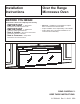
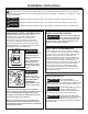
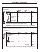
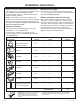
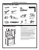
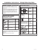
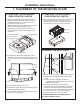
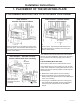

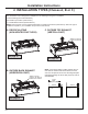
Table Of Contents

31-7000188 Rev. 0 9
D. MARKING THE MOUNTING HOLES
CAUTION
Wear gloves to avoid cutting fingers
on sharp edges.
WARNING
Risk of electric shock. Can cause
injury or death. Take care to not drill into electrical
wiring inside walls or cabinets.
This Rear Wall Template serves to locate the mounting
holes for the bottom mounting plate and to locate the
horizontal exhaust outlet.
1. Use a level to check that the template is positioned
accurately.
2. Locate and mark at least one stud on the left or right
side of the centerline.
NOTE: It is important to use at least one wood screw
mounted firmly in a stud to support the weight of the
microwave.
3. Mark the hole location on the wall using the template at
holes A and B. Mark at least one location in area E that
lines up with the location of a stud. A minimum of three
holes must be used for mounting.
NOTE: Holes A and B are inside area E. If neither
of Holes A and B are in a stud, then find a stud
somewhere in area E and draw a circle to line up with
the stud. It is important to have at least one wood
screw mounted firmly in a stud to support the weight
of the oven.
4. Drill holes in the marked locations. Where there is a
stud, drill a 3/16” hole for wood screws. For holes that
do not line up with a stud, drill 5/8” holes for toggle
bolts.
NOTE: DO NOT INSTALL THE MOUNTING PLATE AT
THIS TIME
5. Remove the template from the rear wall.
Installation Instructions
1. PLACEMENT OF THE MOUNTING PLATE
Hole B
Centerline
notches
Draw a Vertical Line
on Wall from Center
of Top Cabinet
C
L
3/8" TO EDGE
NOTE: IT IS VERY IMPORTANT TO
READ AND FOLLOW THE DI
RECTIONS
IN THE INSTALLATION INSTRUCTIONS
BEFORE PROCEEDI
NG WITH
THIS
REAR WALL TEMPLATE.
This Rear Wal
l Template serves t
o position the bottom
mounting plate and to locate
the horizontal exhaust
outlet.
1. Use a level to check th
at the template is positioned
accurately.
2. Locate and ma
rk at least one stud on the left or
right side of the centerlin
e.
It is important to use at least one wood
screw mounted firmly in a stud to s
upport the weight
of the microwave. Mark two add
itional, evenly spaced
locations for the supp
lied toggle bolts.
3. Drill holes in the marked locatio
ns. Where there is
a stud, drill a 3/16" hole for
wood screws. For hole
s
that do not line up with a st
ud, drill 5/8" holes for
toggle bolts.
DO NOT INSTALL THE M
OUNTING PLATE
AT THIS TIME.
4. Remove the tem
plate from the rear wall.
5. Review the Installation Instru
ction book for your
installation situation.
Locate and mark
holes to align with h
oles in the
mounting plat
e.
IMPORTANT:
LOCATE
AT LEAST ONE
STUD ON EITHER SIDE OF
THE CENTERLINE.
MARK THE LOCATION FOR 2
ADDITIONAL, EVENLY
SPACED
TOGGLE BOLTS IN
THE MOUNTING PLATE
AREA.
Locate and mark
holes to align with hol
es in the
mounting plat
e.
IMPORTANT:
LOCATE
AT LEAST ONE
STUD ON EITHER SIDE OF
THE CENTERLINE.
MARK THE LOCATION FOR 2
ADDITIONAL, EVENLY
SPACED
TOGGLE BOLTS IN
THE MOUNTING PLATE
AREA.
Trim the rear
wall template al
ong the dotted
line.
12"
4"
Darle vuelta a la hoja para consultar la
versión en Español.
Draw a horizontal line on wall at the
bottom of “Rear Wall Template”.
Horizontal Line
Hole A
Hole B
Horizontal Line