WALL HOODS SAFETY INFORMATION . . . . . . . . . . . . .3 USING THE HOOD Controls . . . . . . . . . . . . . . . . . . . . . . . . . . . . . . . . . .5 Chef Connect . . . . . . . . . . . . . . . . . . . . . . . . . . . . .5 CARE AND CLEANING Filters . . . . . . . . . . . . . . . . . . . . . . . . . . . . . . . . . . . 6 Surfaces . . . . . . . . . . . . . . . . . . . . . . . . . . . . . . . . . .7 Lights . . . . . . . . . . . . . . . . . . . . . . . . . . . . . . . . . . . .
THANK YOU FOR MAKING GE APPLIANCES A PART OF YOUR HOME. Whether you grew up with GE Appliances, or this is your first, we’re happy to have you in the family. We take pride in the craftsmanship, innovation and design that goes into every GE Appliances product, and we think you will too. Among other things, registration of your appliance ensures that we can deliver important product information and warranty details when you need them. Register your GE appliance now online.
WARNING TO REDUCE THE RISK OF FIRE, ELECTRIC SHOCK OR INJURY TO PERSONS, OBSERVE THE FOLLOWING: A. Use this unit only in the manner intended by the manufacturer. If you have questions, contact the manufacturer. B. Before servicing or cleaning unit, switch power off at service panel and lock the service disconnecting means to prevent power from being switched on accidentally.
SAFETY INFORMATION IMPORTANT SAFETY INFORMATION READ ALL INSTRUCTIONS BEFORE USING WARNING TO REDUCE THE RISK OF A C. When cutting or drilling into wall or ceiling, do not damage electrical wiring and other hidden utilities. RANGE TOP GREASE FIRE: D. Ducted fans must always be vented to the outdoors. A. Never leave surface units unattended at high settings. Boilovers cause smoking and greasy spillovers that may ignite. Heat oils slowly on medium settings. E.
1 2 6 4 5 3 1. Rangehood Control Panel: The control panel 5. Chef Connect: This is a Bluetooth® pairing feature is located on the front of the canopy. The position and function of each control button are noted below. for use with other compatible Chef Connect enabled products on a cooktop or range. When the device is paired, the light and fan will turn ON at the Default Sync Settings upon receiving a command from the range or cooktop. It will remain ON at that setting until the user changes it.
CARE AND CLEANING: Filters Filters Be sure the circuit breaker is off and all surfaces are cool before cleaning or servicing any part of the vent hood. Metal Grease Filter The metal filters trap grease during cooking. The filters must ALWAYS be in place when the hood is in use. The grease filters are dishwasher-safe and should be cleaned every month, depending on usage of the hood. To remove: Disengage the filter lock to release the filter.
Stainless Steel Surfaces Do not use a steel wool pad; it will scratch the surface. Use only a liquid cleanser free of grit and rub in the direction of the brush lines with a damp soft sponge. To clean the stainless steel surface, use warm sudsy water or a stainless steel cleaner or polish. Always wipe the surface in the direction of the brush line. Follow the cleaner instructions for cleaning the stainless steel surface.
INSTALLATION INSTRUCTIONS Installation Instructions Wall Hoods UVW8301, UVW8361 “If you have questions, call GE Appliances at 800.GE.CARES (800.432.2737) or visit our website at: GEAppliances.com” BEFORE YOU BEGIN Read these instructions completely and carefully. Ŷ IMPORTANT — Save these instructions for local inspector’s use. Ŷ IMPORTANT — Observe all governing codes and ordinances. Ŷ Note to Installer – Be sure to leave these instructions with the Consumer.
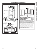
PRODUCT DIMENSIONS INSTALLATION CLEARANCES These vent hoods are designed to be installed onto a wall with no above cabinets. 12-1/4Ǝ 26-5/8Ǝ min. - 39-1/8Ǝ max. 4-5/8Ǝ 25-3/4Ǝ 13-13/16Ǝ 24” Required Min. 36” Recommended Max. 2-3/4Ǝ 20Ǝ 30Ǝ RU Ǝ Grease Filters (quantity may vary by model) 8Ǝ 6-15/16Ǝ 12-7/8Ǝ 10-5/8Ǝ 20Ǝ The vent hood must be installed between the 24” required minimum and 36” recommended maximum above the cooking surface.
INSTALLATION PREPARATION Installation Preparation TOOLS AND MATERIALS REQUIRED (NOT SUPPLIED) PLAN THE INSTALLATION CAUTION To reduce risk of fire and to properly exhaust air, be sure to duct the air outside. Do not vent exhaust air into spaces within walls or ceilings or into attics, crawl spaces, or garages.
RANGE HOOD COMPONENTS INSTALLATION DIMENSIONS A. B. C. D. E. The Wall Hoods duct covers can be adjusted for different ceiling heights depending on the distance between the bottom of the hood and the cooktop (distance X). See Installation Height Table. Wall Hood Upper Duct Cover Lower Duct Cover Mounting Screws Duct Cover Mounting Bracket F. Damper G. Hood Mounting Bracket H. Mounting Anchors J. Machine Screws K. Recirculation Box L.
INSTALLATION PREPARATION Installation Preparation INSTALLATION HEIGHT TABLE Installation Height with Supplied Duct Covers (UX10DC93SS) (UX12DC93SS) (UX14DC93SS) Optional High Ceiling Duct Cover up to 10 ft. (not included with unit) Optional High Ceiling Duct Cover up to 12 ft. (not included with unit) Optional High Ceiling Duct Cover up to 14 ft. (not included with unit) Ceiling Height (ft./in.) Possible Vented Install Height (in.
ADVANCE PLANNING POWER SUPPLY Duct Install Planning IMPORTANT – (Please read carefully) Ŷ This hood is designed to be vented vertically through the ceiling. Use an 8" round duct. Use locally supplied elbows to vent horizontally through the rear wall. Ŷ Use metal ductwork only. WARNING FOR PERSONAL SAFETY, THIS APPLIANCE MUST BE PROPERLY GROUNDED. Ŷ Determine the exact location of the vent hood. Remove house fuse or open circuit breaker before beginning installation.
INSTALLATION Installation NEW CONSTRUCTION, PRE-PLANNING, OR REMODELING NOTE: For existing construction, skip to the section, Installing The Hood Bracket Mount. Ŷ Install horizontal wood supports between 2 wall studs that align with the vertical mounting height locations shown in the illustration. Ŷ The bottom support aligns with the hood mounting bracket. This height depends on the desired height of the hood. Ŷ The horizontal supports must be flush with the room side studs.
INSTALLING THE HOOD BRACKET MOUNT Hood Body 1. Put a protective covering over the surface below the location of the hood to protect from dirt and/or damage. 2. Determine and mark the centerline (C) on the wall (draw line up to the ceiling) where the range hood will be installed. Based on the ceiling height, determine the distance between 24” required min, 36” recommended max (X) needed between the cooking surface (B) and the bottom of the hood. Draw a horizontal line at X.
INSTALLATION Installation INSTALLING THE HOOD Remove the grease filters from the unit and set aside. The grease filters are removed by pressing the handle in the front of the filter. When replacing, make sure that the filters are properly positioned with the handles in front and visible. 1. Securely press the damper on top of the exhaust opening. Check that the damper opens freely. Attach damper to hood using machine screws (J) provided.
INSTALLING THE HOOD (Cont.) A INSTALLATION Installation ELECTRICAL CONNECTION 1. Remove the electrical junction box cover. Vented Installations Connect the house ducting to the damper on the hood body. Seal all connections with duct tape. Ceiling House Ducting 2. Remove the electrical box knockout.
INSTALLATION Installation INSTALL DUCT COVERS 1. For ducted and recirculation installation: Remove protective film from duct covers. Place the upper duct cover so that it slides down inside of the lower duct cover. NOTE: For recirculation, the upper duct cover must be installed with the exhaust vents on the top towards the ceiling. Depending on the amount of overlap between the top and bottom duct covers, the top may be reversed to hide vent holes. Refer to Installation Height Table for possible heights.
Save time and money! Review the charts on the following pages first and you may not need to call for service. Problem Possible Cause What To Do Fan/Light does not operate when button is turned ON A house fuse may be blown or a circuit breaker tripped. Replace fuse or reset circuit breaker. Loud or abnormal airflow noise Wrong duct size used in installation. This hood requires 8” ducting to perform optimally. Using smaller duct pipe will cause reduced venting.
Notes 20 49-80816
Notes 49-80816 21
WARRANTY GE Appliances Vented Range Hood Warranty GEAppliances.com All warranty service is provided by our Factory Service Centers, or an authorized Customer Care® technician. To schedule service online, visit us at www.geappliances.com/service_and_support/, or call GE Appliances at 800.GE.CARES (800.432.2737). Please have your serial number and your model number available when calling for service. Servicing your appliance may require the use of the onboard data port for diagnostics.
Looking For Something More? GE Appliances offers a variety of accessories to improve your cooking and maintenance experiences! Refer to the Consumer Support page for phone numbers and website information.
CONSUMER SUPPORT Consumer Support GE Appliances Website Have a question or need assistance with your appliance? Try the GE Appliances Website 24 hours a day, any day of the year! You can also shop for more great GE Appliances products and take advantage of all our on-line support services designed for your convenience. In the US: GEAppliances.
CAMPANAS DE PARED INFORMACIÓN DE SEGURIDAD . . . .3 USO DE LA CAMPANA MANUAL DEL PROPIETARIO E INSTALACIÓN CUIDADO Y LIMPIEZA UVW8301 UVW8361 Controles . . . . . . . . . . . . . . . . . . . . . . . . . . . . . . . . . 5 Chef Connect . . . . . . . . . . . . . . . . . . . . . . . . . . . . . 5 Filtros . . . . . . . . . . . . . . . . . . . . . . . . . . . . . . . . . . . .6 Superficies . . . . . . . . . . . . . . . . . . . . . . . . . . . . . . . . 7 Lámparas . . . . . . . . . . . . . . . . . . . . . .
GRACIAS POR HACER QUE GE APPLIANCES SEA PARTE DE SU HOGAR. Ya sea que haya crecido usando GE Appliances, o que ésta es su primera vez, nos complace tenerlo en la familia. Sentimos orgullo por el nivel de arte, innovación y diseño de cada uno de los electrodomésticos de GE Appliances, y creemos que usted también. Entre otras cosas, el registro de su electrodoméstico asegura que podamos entregarle información importante del producto y detalles de la garantía cuando los necesite.
ADVERTENCIA PARA REDUCIR EL RIESGO DE INCENDIO, DESCARGA ELÉCTRICA O LESIONES A PERSONAS, CUMPLA CON LOS SIGUIENTES PUNTOS: A. Utilice esta unidad sólo de la manera concebida por el fabricante. Si tiene alguna pregunta, comuníquese con el fabricante. B. Antes de realizar reparaciones o limpiar la unidad, desconecte la energía del panel de servicio y bloquee los medios de desconexión para evitar el accionamiento de la energía de manera accidental.
INFORMACIÓN DE SEGURIDAD INFORMACIÓN IMPORTANTE DE SEGURIDAD LEA TODAS LAS INSTRUCCIONES ANTES DE USAR ADVERTENCIA PARA REDUCIR EL RIESGO DE UN INCENDIO DE GRASA SOBRE UNA ESTUFA: A. Nunca deje unidades de superficie desatendidas en configuraciones de calor elevadas. Los alimentos que hierven y se derraman provocan humo y derrames grasosos que pueden prenderse fuego. Caliente los aceites lentamente en configuraciones bajas o medias. B.
1 2 6 4 3 1. Panel de Control de la Campana Extractora: 5. Chef Connect: Ésta es una función de emparejamiento de Bluetooth® para uso con otros productos compatibles con Chef Connect en una superficie de cocción o una cocina. Cuando el dispositivo es emparejado, la luz y el ventilador se encenderán en Default Sync Settings (Configuraciones de Sincronización por Omisión), al recibir una orden desde la cocina o la superficie de cocción.
CUIDADO Y LIMPIEZA: Filtros Filtros Asegúrese de que la energía eléctrica esté apagada y que todas las superficies estén frías antes de limpiar o arreglar cualquier pieza de la campana de ventilación. Filtro de grasa metálico Los filtros metálicos atrapan la grasa durante la cocción. Filtro debe estar SIEMPRE en su lugar cuando la campana esté en funcionamiento. Los filtros de grasa son de uso seguro en lavavajillas y deberán ser limpiados cada mes, dependiendo del uso de la campana.
Superficies de acero inoxidable No utilice almohadillas de acero porque rayan la superficie. Para limpiar la superficie de acero inoxidable, utilice agua tibia jabonosa o un limpiador o lustrador de acero inoxidable. Siempre limpie la superficie en dirección de la veta. Siga las instrucciones del producto para limpiar la superficie de acero inoxidable. Los limpiadores con ácido oxálico tales como Bar Keepers Friend Soft Cleanser™ eliminarán el óxido sobre la superficie, deslustres y pequeñas manchas.
INSTRUCCIONES DE INSTALACIÓN Instrucciones de instalación Campanas de Pared UVW8301, UVW8361 “Ante cualquier duda, llame a GE Appliances al 800.GE.CARES (800.432.2737) o visite nuestro sitio Web en: GEAppliances.com” ANTES DE COMENZAR Lea estas instrucciones por completo y con detenimiento. IMPORTANTE Ŷ — Guarde estas instrucciones para el uso de inspectores locales. Ŷ — Cumpla con todos los códigos y ordenanzas vigentes.
DIMENSIONES DEL PRODUCTO ESPACIO DE INSTALACIÓN Estas campanas de ventilación están diseñadas para ser instaladas en una pared sin gabinetes superiores. 12-1/4Ǝ 26-5/8Ǝ mín. - 39-1/8Ǝ máx.
PREPARACIÓN PARA LA INSTALACIÓN Preparación para la instalación HERRAMIENTAS Y MATERIALES REQUERIDOS (NO SUMINISTRADOS) Gafas de seguridad Lápiz y cinta métrica PLAN DE INSTALACIÓN ADVERTENCIA A fin de reducir riesgos de incendios y para que el aire salga de forma apropiada, asegúrese de que el aire sea conducido hacia fuera.No ventile el aire de la salida hacia espacios dentro de paredes o cielorrasos o áticos, espacios muy bajos o garajes.
COMPONENTES DE LA CAMPANA EXTRACTORA A. Sección de la Base B. Cubierta del Conducto Superior C. Cubierta del Conducto Inferior D. Tornillos de Montaje E. Soportes de Montaje de la Cubierta del Conducto F. Regulador G. Soporte de Montaje de la Campana H. Anclaje del Montaje J. Tornillos para Metal K. Caja de Recirculación L.
PREPARACIÓN PARA LA INSTALACIÓN Preparación para la instalación TABLA DE ALTURAS DE INSTALACIÓN Altura de Instalación con Tapas de Conductos Suministradas Altura Posible de Instalación Altura Ventilada Posible de Instalación (Recirculación ventilada con con Agujero Recirculación Oculto) (pulg.) (pulg.
PLANIFICACIÓN PREVIA SUMINISTRO DE ENERGÍA Planificación para la Instalación con Conducto IMPORTANTE – (Tenga a bien leer cuidadosamente) Ŷ Esta campana está diseñada para ventilarse en forma vertical a través del cielorraso. Use un conducto circular de 8”. Utilice codos suministrados en forma local para ventilación horizontal a través de la pared trasera. Ŷ Determine la ubicación exacta de la campana de ventilación. Ŷ Planifique el recorrido de la salida de ventilación hacia el exterior.
INSTALACIÓN Instalación NUEVA CONSTRUCCIÓN, PLANIFICACIÓN PREVIA O REMODELACIÓN NOTA: Para construcciones existentes, pase a la sección de Instalación del Montaje del Soporte de la Campana. Ŷ Instale soportes de madera horizontales entre 2 montajes de pared que se alineen con las ubicaciones de la altura del montaje vertical mostrado en la ilustración. Ŷ El soporte inferior se alinea con el soporte de montaje de la campana. La altura depende de la altura deseada de la campana.
INSTALACIÓN DEL MONTAJE DEL SOPORTE DE LA CAMPANA Cuerpo de la Campana Tapas del Conducto y Suministro de Corriente 1. Coloque una tapa protectora sobre la superficie que se encuentra debajo de la ubicación de la campana, a fin de proteger la misma de la suciedad y/o daños. 1. Coloque el soporte de la tapa del conducto (E) en la pared, de modo que su extremo se encuentre contra el cielorraso y nivelado, asegurándose de que las ranuras se encuentren en contacto directo con la pared.
INSTALACIÓN Instalación INSTALACIÓN DE LA CAMPANA Retire los filtros de grasa de la unidad y deje los mismos a un costado. Los filtros de grasa deben ser retirados presionando la manija ubicada en el frente del filtro. Al realizar el reemplazo, asegúrese de que los filtros queden correctamente posicionados con las manijas en frente y visibles. 1. De forma segura, presione el regulador ubicado en la parte superior de la abertura del extractor. Controle que el regulador se abra libremente.
INSTALACIÓN DE LA CAMPANA (Cont.) A INSTALACIÓN Instalación CONEXIÓN ELÉCTRICA 1. Retire la tapa de la caja de empalmes eléctricos. Instalaciones Ventiladas Conecte el conducto hogareño al regulador ubicado en el cuerpo de la campana. Selle todas las conexiones con cinta para conductos. Cielorraso Conducto Hogareño 2. Retire el tablero de la caja eléctrica.
INSTALACIÓN Instalación INSTALACIÓN DE LAS TAPAS DE LOS CONDUCTOS 1. Para la instalación con conducto y recirculación: Retire la capa protectora de las tapas del conducto. Coloque la tapa del conducto superior, de modo que se deslice dentro de la tapa del conducto inferior. NOTA: Para la recirculación, la tapa del conducto superior deberá ser instalada con las ventilaciones del extractor en la parte superior hacia el cielorraso.
¡Ahorre tiempo y dinero! Primero revise los cuadros que aparecen en las siguientes páginas y es posible que no necesite solicitar reparaciones. Problema Causas posibles Qué hacer El Ventilador/ la Luz no funciona cuando el botón está en ON (Encendido) El fusible puede haberse quemado o el interruptor decircuitos puede haber saltado. Cambie los fusibles o reconfigure el interruptor de circuitos. Ruido de flujo de aire muy elevado o anormal Tamaño de conducto incorrecto utilizado en la instalación.
Notas 20 49-80816
Notas 49-80816 21
GARANTÍA Garantía de la Cocina Eléctrica de GE Appliances GEAppliances.com Todo el servicio de garantía es provisto por nuestros Centros de Servicio de Fabricación, o un técnico autorizado de Customer Care®. Para programar una visita del servicio técnico a través de Internet, visítenos en www.geappliances.com/service_and_support/, o llame al 800.GE.CARES (800.432.2737). Cuando llame para solicitar el servicio, tenga los números de serie y modelo disponibles.
¿Busca Algo Más? GE Appliances ofrece una variedad de accesorios para mejorar sus experiencias de cocción y mantenimiento! Para acceder a números telefónicos e información de sitios Web, consulte la página de Soporte para el Consumidor.
SOPORTE PARA EL CONSUMIDOR Soporte para el Consumidor Sitio Web de GE Appliances ¿Desea realizar una consulta o necesita ayuda con su electrodoméstico? ¡Intente a través del Sitio Web de GE Appliances las 24 horas del día, cualquier día del año! Usted también puede comprar más electrodomésticos maravillosos de GE Appliances y aprovechar todos nuestros servicios de soporte a través de Internet, diseñados para su conveniencia. En EE.UU.: GEAppliances.