
Installation guide


Installation Instructions
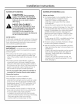
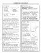
WATER SUPPLY
• A cold water
supplg is required
for icemaker
operation. The
water pressure
must be between
30 and !20 p.s.k
• Route GE
Sma rtCon nect T" Water Supply Should
Kit or !/4" O.D. Enter From Back Wall
In Shaded Area.
copper tubing
between house cold water line and the water
connection locution.
• The water line should be long enough to extend
to the buck of the icemoker. Allow enough to
accommodate moving unit forward for service.
NOTE: The onlg GEapproved plastic tubing is supplied
in the GESmartConnect" Refrigerator Tubing kits. Do
not use ang other plastic water supplg line because the
line is under pressure at all times. Other tgpes of plastic
nag crack or rupture with age and cause water
damage to gour home. GESmartConnecf" Refrigerator
Tubing Kits are available in the following lengths:
2' (0.6 m) WX08Xl0002 15' (4,6 m)WX08X10015
6' (1.8 m) WX08X10006 25' (7,6 m)WX08X]0025
Shut offthe main water supply
Turn on the nearest faucet long enough to clear the
line of water.
Install a shut-off valve between the icemaker water
valve and cold water pipe in a basement or cabinet.
The installation of an easilg accessible shut-off
valve in the water line is required.
NOTE: It is best to install the valve into a vertical
water pipe. If gou install the valve into a horizontal
water pipe, make the connection at the top or side,
rather than at the bottom, to avoid drawing off ang
sediment from the water pipe.
• Turn on the main water supplg and flush debris from
the line. Run about a quart of water through the
tubing into a bucket. Shut off water supplg at the
shut-off valve.
NOTE: Saddle tgpe shut-off valves are included in
mang water supplg kits, but are not recommended
for this application.
NOTE: Commonwealth of Massachusetts Plumbing
Codes 248CHR shall be adhered to. Saddle valves
are illegal and use is not permitted in Hassachusetts.
Consult with gour licensed plumber.
• Install optional water filter in the water line near
the icemaker. A water filter is recommended in areas
where water supplg contains sand or particles.
Installation instructions are packed with the filter.
WATER SUPPLY (cont.)
REVERSEOSMOSIS WATER SUPPLY
IM PORTANT: The performance of the icemaker
mag be affected when it is connected to a reverse
osmosis sgstem.
• The pressure of the water supplg coming out of a
reverse osmosis sgstem going to the water inlet valve
of the icemaker needs to be between 30 and 120 psi.
• If a reverse osmosis water filtration sgstem is
connected to gour cold water supplg, the water
pressure to the reverse osmosis sgstem needs to
be a minimum of 40 to 60 psi. The reverse osmosis
sgstem must provide i gal. of water per hour to
the icemaker for proper icemaker operation.
• Do not use copper tubing when the icemaker is
connected to a reverse osmosis water system.
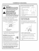
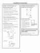
CONNECT DRAIN
1¸-
This icemaker is
equipped with a gravitg
drain to prevent water
from flowing back into
the storage bin and
overflowing onto the
floor, The ideal I ":,)
installation has a 2"
standpipe with a
to 1-1/2" PVC drain
reducer installed directlg
below the drain tube: customPanel
/Drain Hose
1" Min. Gap
-A 1" min. phgsical gap
between the bottom of
the icemaker drain hose
and the top of the house
drain is required. See
illustration.
-7-1/2" to centerlJne LocateStandpipein Exact
Centerof the Icemaker
of the opening. _lf you haveinstalledacustompanel
-Approximatelg 3-1/2" high. andthe 1-1/2"filler strip,positionthe
drainat the exactcenterof the product.
-22" from the front, or
22-3/4" when installing a 3/4" door panel.
• Drain lines must be at least 5/8" inside diameter.
NOTE: A drain pump is necessarg when a floor
drain is not available. Order ZPK1 Drain Pump Kit
or contact gour local plumber for a recommended
pump available in gour area.
TEST DRAIN HOSE ALIGNMENT: Before sliding the
icemaker into the cabinet opening, check to be sure
the bottom of the drain tube is below the rear cover.
To test, place a pan below the drain hose. Pour a
gallon of water into the ice bin and check to be sure
that water does not wet the rear cover.