Installation Instructions 30” Built-In Wall Oven ZET1, ZET2 If you have questions, call 1.800.GE.CARES or visit our website at: ge.com Before You Begin • Proper installation is the responsibility of the installer and product failure due to improper installation is NOT covered under warranty. • NOTE—This appliance must be properly grounded. Read these instructions carefully and completely. • IMPORTANT—Save these instructions for local inspector’s use.
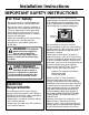
Installation Instructions IMPORTANT SAFETY INSTRUCTIONS For Your Safety This appliance must be supplied with the proper voltage and frequency, and connected to an individual, properly grounded branch circuit, protected by a circuit breaker or fuse having amperage as noted on rating plate. • Be sure your oven is installed properly by a qualified installer or service technician. • Be sure the oven is securely installed in a cabinet that is firmly attached to the house structure.
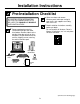
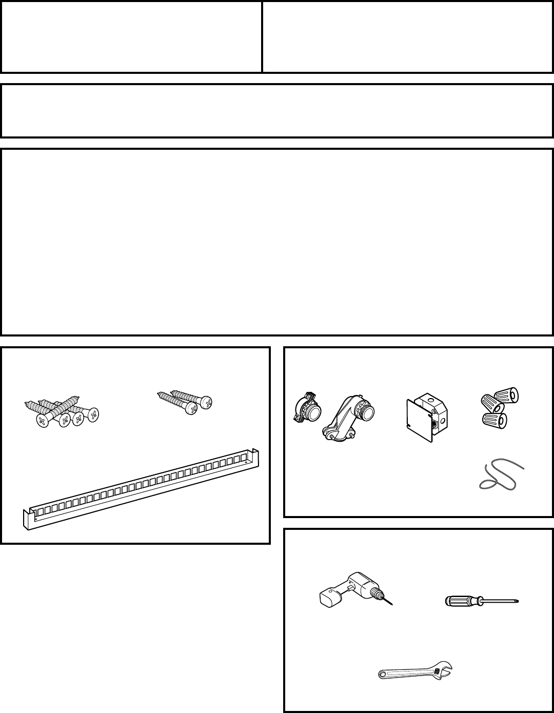
Installation Instructions Pre-Installation Checklist Open oven door and remove literature pack, broiler pan and grid, oven racks, rack supports and a bag with 9 hex nuts. ALL INSTALLATION INFORMATION ON THE FOLLOWING PAGES IS TO BE USED FOR SINGLE AND DOUBLE OVEN INSTALLATION! Read Installation Instructions carefully before you begin. Be sure to place all literature, Owner’s Manual, Installations, etc. in a safe place for future reference. Remove packaging materials.
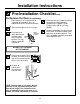
Installation Instructions Pre-Installation Checklist cont. To Remove the Door (if necessary) Place the oven on a table or platform even with the cutout opening. (Platform must support 175 lbs. [79 kg] single, 350 lbs. [159 kg] double.) Door removal is not a requirement for installation of the product, but is an added convenience. To remove the door: Open the oven door as far as it will go. Push both hinge locks down toward Hinge the door frame, Hinge Slot Slot to the unlocked position.
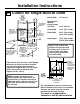
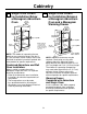
Installation Instructions A1 Cutout for Single Built-In Oven Cutout Width 28 1/2” Min. 28CUTOUT 5/8” Max. WIDTH to 28(72.4 1/2" MIN. 2872.7 5/8" cm) MAX. Cabinet Width (12.7 cm) JUNCTION BOX Junction Box LOCATION Location ALLOW 11/16" FOR OVERLAP OF THE Allow 11/16” OVEN OVER SIDE (1.75 for EDGES OFcm) CUTOUT overlap of oven over side edges of cutout Opening Between THE OPENING Inside Walls BETWEEN INSIDE Must Be WALLS MUST BEAt ATLeast LEAST 28 281/2"WIDE 1/2” (72.
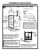
Installation Instructions A2 Cutout for Double Built-In Oven Cutout Width 28 1/2” CUTOUT (72.4 cm) Min. WIDTH 28 1/2" MIN. 28 5/8” 28 5/8" MAX. (72.7 cm) Max. Cabinet Width 30” (76.2 cm) 5” 5" (12.7 cm) Junction Box JUNCTION BOX Location LOCATION ALLOW 11/16" FOR OVERLAP Allow OF THE11/16” OVEN OVER (1.8SIDE cm) EDGES for OF CUTOUT overlap of oven over side edges of cutout Allow a minimum ALLOW A MINIMUM OF 21" of 21” (53.
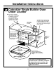
Installation Instructions A3 Cutout for Single Built-In Oven Under Counter Gas or electric cooktops mayGas be or installed over thismay electric cooktops be See installed over this oven. oven. cooktop installation See cooktop instructions forinstallation cutout size. instructions for cutout size. See See label on top of oven for label on top of oven for approved cooktop approved cooktopmodels. models.
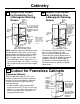
Cabinetry A4 Single Oven Cutout A5 for Installation Over a Monogram Warming 23 1/2” Drawer (59.7 cm) Min. Inside 9” (22.9 cm) Max. Min. Inside 2” x 2” (5 cm x 5 cm) or 2” x 4” (5 cm x 10 cm) Anti-Tip Block Against Rear Wall, 9” (22.9 cm) From Floor to Bottom of Block 27 5/16” (69.2 cm) Max. 9 1/4” (23.5 cm). 28 1/2” (72.4 cm). Double Oven Cutout for Installation Over a Monogram Warming 23 1/2” Drawer (59.7 cm) 2” (5.1 cm) Min. Allow 5/8” (1.5 cm) Overlap on All Sides 51 15/16” (131.8 cm) Max.
Cabinetry A7 Single Oven Cutout for Installation Below a Monogram Advantium 23 1/2” Oven (59.7 cm) A8 Min. Inside Single Oven Cutout for Installation Between a Monogram Advantium Oven and a Monogram Warming Drawer 23 1/2” (59.7 cm) Min. Inside Per Advantium Requirement Per Advantium Requirement 2” (5.1 cm) Min. 2” (5.1 cm) Min. 45 1/4” (114.9 cm) 27 5/16” (69.2 cm) Max. 28 1/2” (72.4 cm) Note: Install the oven only with specific models listed on the label located on top of the oven. 45 1/4” (114.
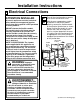
Installation Instructions B Electrical Connections ATTENTION INSTALLER All electric wall ovens must be hard wired (direct wired) into an approved junction box. A plug and receptacle is NOT permitted on these products. DO NOT shorten the flexible conduit. The conduit strain relief clamp must be securely attached to the junction box and the flexible conduit must be securely attached to the clamp.
Installation Instructions B Electrical Connections cont. B3 New Construction and B4 Four-Conductor Branch Circuit Connection • When installing in new construction, or B5 • When installing in a mobile home, or This oven is supplied with a 48” (123 cm) long flexible conduit consisting of: 3 insulated conductors (copper) 1 bare ground conductor (copper) Attach conductors to residence wiring as shown by wiring diagram.
Installation Instructions C Securing the Oven in the Opening C1 Sliding the Oven Into C2 Drilling the Pilot Holes the Opening and Mounting the Oven a. Loop (do not tie) a 36” (91 cm) string around the conduit before the oven is slid into place. This will keep the conduit from falling behind the oven. NOTE: Before drilling the pilot holes, make sure the oven is pushed as far back into the opening as it will go and centered. a.
Installation Instructions C3 Installing the Oven C4 Installing the Metal Rack Supports and Oven Racks Bottom Trim a. Place the bottom trim between the side trim and against the bottom of the cutout. Oven Rack Supports b. Using two trim screws provided, secure the bottom trim to the bottom edge of the cabinet. Place the rack support with the slotted holes over the rear bolts and the round holes over the front bolts.
Installation Instructions D Replacing the Oven Door NOTE: The oven door is heavy. You may need help lifting the door high enough to slide it into the hinge slots. Do not lift the door by the handle. D1 D3 Open the oven door as far as it will open. D4 Push the hinge locks up against the front frame of the oven cavity, to the locked position. Hinge in Locked Position Lift the oven door by placing one hand on each side. The door is heavy, so you may need help. Do not lift the door by the handle.
Installation Instructions Pre-Test Checklist Remove all protective film, if present, and any stickers. Check that the bottom trim is installed properly (see page 13). Check to be sure that all wiring is secure and not pinched or in contact with moving parts. Check to be sure the mounting screws are installed and flush with the side trim (see page 12). NOTE TO ELECTRICIAN: You must unplug the green wire (near where the long flexible conduit exits the unit) when conducting high-potential testing.
Printed in U.S.A.