Installation Instructions Professional Style Bottom-Freezer Refrigerators ZICP720 Design Guide With Installation Instructions monogram.
Safety Information Skill Level — Installation of these refrigerators requires basic mechanical, carpentry and plumbing skills. Proper installation is the responsibility of the installer. Product failure due to improper installation is not covered under the GE Appliance Warranty. See the Owner’s Manual for warranty information. BEFORE YOU BEGIN Read these instructions completely and carefully. • IMPORTANT — Save these instructions for local inspector’s use. Observe all governing codes and ordinances.
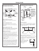
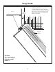
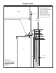
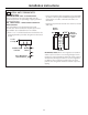
Design Guide THE INSTALLATION SPACE DIMENSIONS AND CLEARANCES The installation space must be 71-1/2″. 71-1/2″ Case Width 25-3/4″ Case Depth 71-1/2″Finished FinishedWidth Width 71-1/2" 2-5/16" 2-5/16″ Electrical Electrical 6″ 6" 84-1/2" max 84-1/2″ max 83-1/2" min 83-1/2″ min Finished Finished Opening Opening 10" 10″ 24″ CutoutDepth Depth 24" Cutout 3-1/2″ 3-1/2" 5″ 5" 10" 10″ 24-3/16" 24-3/16″ 6″ 6" 10" 10″ 3-1/2″ 3-1/2" 3-1/2" 3-1/2″ 5″ 5" 5″ 5" 3-1/2″ 3-1/2" 5″ 5" * Shipping height.
Design Guide Refrigerator Frameless Cabinets: The case trim overlaps cabinets at the top and sides. Therefore, frameless cabinets may require filler strips to prevent interference with cabinet door swing. The opening must allow for filler strips.
Design Guide Frameless Cabinets: The case trim overlaps cabinets at the top and sides. Therefore, frameless cabinets may require filler strips to prevent interference with cabinet door swing. The opening must allow for filler strips.
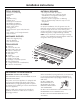
Installation Instructions TOOLS REQUIRED MATERIALS REQUIRED • Tinsnips to cut banding • Stepladder • Bucket • Level • Appliance dolly • Tubing cutter • 7/16″ open-end wrench • #2 Phillips screwdriver • Drill and appropriate bits • 5/16″, 7/16″ socket • Safety glasses • 1-1/4″ and 1/2″ open-ended wrench • Pliers • 1/4″ ratchet or 1/4″ angled wrench • Tape measure • 71″ long 2x4 for Anti-Tip support • 1/4″ copper water line tubing or two GE SmartConnect™ Refrigerator Tubing kits • Two water shut-off valves
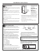
Installation Instructions • Remove the four 7/16″ bolts securing the straps to the skid. 1 REMOVE PACKAGING CAUTION: Refrigerator is much heavier at the top than at the bottom—be careful when moving. When using a hand truck, handle from side only. CAUTION: DO NOT Remove Tie-Downs PRUDENCE : Le réfrigérateur est beaucoup plus lourd en haut qu'en bas. Il faut être prudent lors des déplacements. Si un diable est utilisé, il faut soulever le réfrigérateur sur le côté seulement.
Installation Instructions 3 INSTALL NEW SIDE TRIM CAUTION: Handle parts with care to avoid scratching. PRUDENCE : Manipulez les pièces soigneusement pour éviter de les rayer. Foam Spacer Pads B. Apply the supplied foam spacer pads (H) to the mating side of one product as shown. A. Install inside case trims (B & C) with notches toward the bottom. Install screws (I) through 5 slots on each trim. 4 INSTALL SIDE PANELS * Depending on installation height.
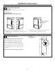
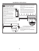
Installation Instructions 5 INSTALL ANTI-TIP BRACKETS WARNING: ANTI-TIP PRECAUTIONS • Secure the bracket with wood block to the back wall so that it is 84″ (or your installation height) from the finished floor. Use #12 or #14 wood screws. See illustration. These refrigerators are top-heavy and must be secured to prevent the possibility of tipping forward. ATTENTION : PRECAUTIONS CONTRE LES • Screws must penetrate at least one inch into vertical wall studs.
Installation Instructions 6 POSITION REFRIGERATOR AND INSTALL TOP TRIM • Before pushing the refrigerators into the Approx. 8″ opening, plug the power cords into the receptacles. Reach into the top opening Soffit to grasp the power cord. Pull the power cord into the opening as you push the refrigerator back. • With hands against front corners, push one refrigerator part-way into the opening. The refrigerator should be approximately 8″ forward of the back wall.
Installation Instructions 7 LEVEL THE REFRIGERATORS • When refrigerators are level, tighten screws against the bracket. Place a level inside the machine for each unit. Both refrigerators MUST BE LEVEL AND PLUMB with each other and with adjacent cabinetry on each side. Drawers should be evenly aligned. Both refrigerators have 4-point leveling. The front is supported by leveling legs, the rear is supported by adjustable wheels. Both are accessible from the front of the refrigerator.
Installation Instructions 8 ALTERNATE ANTI-TIP PROCEDURE The refrigerator must be secured to prevent tipping. 3/4″ Min. The anti-tip brackets cannot be used on metal wall studs. Use this Alternate Procedure to secure the refrigerator against tip-over whenever metal wall studs are encountered and there is a soffit. • Use a 3/16″ bit to drill eight evenly spaced clearance holes through the metal top case trim.
Installation Instructions Case Trim 11 INSTALL CENTER TRIM STRIP • Open doors fully. • The case trims should be evenly aligned top to bottom with a slight gap between them. • Starting at the top, press center trim strip (D) over the inside case trims of both refrigerators. U-Shape Trim • Continue pressing trim until you reach the bottom of the case trims. The trim should align with the top and bottom of case trims. 12 ADJUST DOOR SWING NOTE: This refrigerator has a 2-position door stop.
Installation Instructions 13 CHECK AND CORRECT DOOR ALIGNMENT • Close the grille panel and both doors. • Check that the freezer drawers and bottom of doors are horizontal and even at the lower inside corners. • Carefully measure the inside corners to determine if an adjustment is needed. A difference of 1/32″ is acceptable and does not require adjustment. Spacer Location SKIP THIS STEP IF DOORS ARE LEVEL.
Installation Instructions 13 CHECK AND CORRECT DOOR ALIGNMENT (cont.) RH Fresh Food door is higher than the LH door: CAUTION: Follow instructions very carefully. PRUDENCE : Suivez les instructions très soigneusement. DETERMINE CORRECT SPACER This kit contains 12 plastic spacers (2 of each size). Match spacer to illustration below to be sure you have selected the correct size as determined in the charts below.
Installation Instructions 13 CHECK AND CORRECT DOOR ALIGNMENT (cont.) Remove Pin Lift off and replace plastic spacer 4. Lift door off bottom hinge pin. The door must be held in place while spacers are being exchanged. 5. Remove the original plastic spacer. 6. Place the selected spacer over the hinge. 7. Reverse all steps to replace the door. Remove 4 Screws 1. Open the grille panel. 2. Remove 4 screws on the hinge plate. 3. Use pliers to remove door stop pin.
Installation Instructions 14 INSTALL GRILLE BASE WRAP • Open doors fully. Open the grille panel. • Install the unified double width grille base wrap (E) by slipping the notched ends over the door hinges. • Install one screw (I) on each end and 2 at the center. Unified Grille Base Wrap Place Trim Over Hinges 15 CONNECT WATER SUPPLY Connect both refrigerators to the water supply. • Locate and bring tubing to the front of the cabinet. • Turn the water on to flush debris from line.
Installation Instructions 16 CONNECT POWER 18 INSTALL TOEKICK • Check to be sure the power cord is plugged into the receptacle. • Install the toekick (G) with 4 screws (I) provided, one on each side and 2 in the center. Raise Grille Panel Electrical Outlet IMPORTANT: The toekick must be positioned with the vented slots on the top side. The vented toekick must remain unobstructed for proper air circulation and refrigerator operation.
Notes 19
NOTE: While performing installations described in this book, safety glasses or goggles should be worn. If your Monogram appliance should ever require service, you can depend on Monogram Preferred Service. Simply call 1.800.444.1845 where our Monogram Preferred Service Specialists are available 7 a.m. to 10 p.m. ET Monday through Friday and 8 a.m. to 6 p.m. ET Saturday and Sunday to coordinate your service appointment.