g GE Consumer Home Services Training TECHNICAL SERVICE GUIDE Monogram Side-By-Side Refrigerators With Electronic Controls GEA01265 MODEL SERIES: ZIS360NM ZIS420NM ZIS480NM ZIS_360DM ZIS_420DM ZIS_480DM PUB # 31-9091 03/02
! IMPORTANT SAFETY NOTICE The information in this service guide is intended for use by individuals possessing adequate backgrounds of electrical, electronic, and mechanical experience. Any attempt to repair a major appliance may result in personal injury and property damage. The manufacturer or seller cannot be responsible for the interpretation of this information, nor can it assume any liability in connection with its use. WARNING To avoid personal injury, disconnect power before servicing this product.
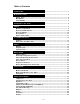
Table of Contents Technical Data ........................................................................................................................ 3 Model Nomenclature .............................................................................................................. 4 Rating Plate ...................................................................................................................... 4 Mini-Manual ..............................................................................
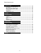
Table of Contents (cont.) Compartment Lights ............................................................................................................. 44 FF/FZ Compartment Lights Diagnostic .......................................................................... 44 Door Switches ................................................................................................................. 45 Master Light Switch (Sabbath Switch) .......................................................................
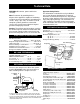
Technical Data Important Safety Notice: WARNING: Disconnect power cord before servicing. This information is intended for use by individuals possessing adequate backgrounds of electrical, electronic, and mechanical experience. Any attempt to repair a major appliance may result in personal injury and property damage. The manufacturer or seller cannot be responsible for the interpretation of this information, nor can it assume any liability in connection with its use. Note: Reconnect all grounding devices.
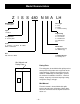
Model Nomenclature Z I S S 480 N M A LH Brand/Product Z - Monogram Door Type F - Flat R - Right L - Left Door Swing Style I - Built-In Engineering A - Initial Design B - 1st Revision C - 2nd Revision D - 3rd Revision Etc.
Serial Number The serial number consists of two letters, followed by six numerals. The two prefix letters of the serial number indicate the month and year the product was manufactured. The year of manufacture does not correspond with the model year of the model number.
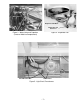
Component Locator Views Compressor Dryer Overload & Condenser Fan PTCR Relay Master Light Switch (Sabbath Switch) Figure 1 - Machine Compartment Evaporator Defrost Heater Evaporator Thermistor Evaporator Overtemperature Thermodisc (TOD) Figure 2 - Evaporator (Top of Freezer) –6–
Water Valve Evaporator Fan Motor Capacitor Evaporator Fan Connector Figure 4 - Evaporator Fan Figure 3 - Water Valve and Capacitor (Center of Machine Compartment) Drawer Under Center of Unit Circuit Breakers Transformers Figure 5 - Light Circuit Transformers –7–
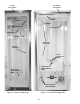
Freezer Door Switch Fresh Food Door Switch Temperature Touch Pad Icemaker Damper Airflow Grille Water Filter Auger Drive Cube Solenoid Fresh Food Thermistors Freezer Thermistor Lower Fresh Food Lights Temperature Overload Device (TOD) Temperature Overload Device (TOD) Climate Control Drawer Fan Climate Control Drawer Dampers Figure 7 - Fresh Food Compartment Figure 6 - Freezer Compartment –8–
Cabinet The outer case is made of prepainted galvanized steel. The fresh food and freezer liners are painted metal with a smooth finish. The liners are not removable or replaceable. Machine Compartment Machine Compartment The machine compartment is located on the top of the unit and has a movable chassis that can be extended from the front of the unit to provide access to the refrigeration system components. Caution: Avoid kinking the refrigeration lines when sliding the chassis out and back in.
Door Closure Mechanism Doors and Hinges The door closure mechanism uses a spring to provide positive door closure from approximately 60 degrees. The door closure mechanism actuator arm has a spring attached to the rear and is supported by guide rollers on either side of the base channel. The roller circumferences and the actuator arm detents are matched for smooth operation. The arm is attached to the door with an Allen head shoulder bolt. The doors are of one-piece construction with foam insulation.
3. Remove T-27 Torx screws (4) and hinge from the bottom of the door. Hinge Bushing Base Channel Spacer Hinge Door Stop 5/16" Bolt GEA01268 Door Gaskets The fresh food and freezer doors have magnetic gaskets that create a positive seal to the front of the steel cabinet. The center mullion also has magnets to assist in door sealing. Improper installation of the door gasket will cause same-poled magnets to oppose one another, preventing the door from closing tightly.
Ice and Water Dispenser The icemaker is mounted to the upper left wall of the freezer cabinet. Under normal operating conditions, temperatures, door openings, and food load, the icemaker is capable of producing approximately 100 to 130 cubes in a 24-hour period. Power Switch Icemaker To service the icemaker, refer to GE Publication 31-9063. Controls The electronic controls on the dispenser are interactive.
Water Valve and Water Tank The water valve is mounted in the left side of the machine compartment. Water Valve Screw A plastic water line is routed from under the unit, up the back of the cabinet, into the machine compartment, and to the water filter. A line then goes from the water filter to the water valve. Two low-pressure plastic water lines supply water to the icemaker and door dispenser from the water valve.
Airflow Damper The fresh food compartment receives chilled air via an electronic damper that is positioned at the top rear of the fresh food compartment. The damper is controlled by the main control board and when open, allows the evaporator fan to push chilled air from the evaporator into the fresh food compartment. To Remove the Damper 1. Remove the light cover. 3. Remove the Styrofoam section covering the damper. 4. Disconnect the damper wiring connector. Damper Screws 2.
Defrost Heater Pin 1 J9 Pin 9 J7 Pin 8 Pin 7 Pin 6 Pin 5 Pin 4 Pin 3 Pin 2 Pin 1 Neutral NIC FZ Door Switch FF Door Switch QuickChill Heater Auger Motor Interlock Water Valve Crusher Solenoid Auger Motor Pin 2 QuickChill Htr. Pin 1 QuickChill Htr.
speed and medium-speed operation. When operating in low and medium speeds, voltage is sent in pulses (much like a duty cycle) as opposed to an uninterrupted flow. This pulsing of 12.6 VDC produces effective voltage being received at the motor, which is the equivalent to a reduction in voltage. Fan speed will be selected and maintained by the control board regulating the length and frequency of the 12.6 VDC pulse. One complete revolution of the motor is comprised of all 4 poles.
J1 Pin 1 Pin 2 Pin 3 Pin 4 Pin 5 Pin 6 Pin 7 Pin 8 Pin 9 FF1 Thermistor FF2 Thermistor FZ Thermistor Evaporator Thermistor +5V Personality Input 1 Personality Input 2 Personality Input 3 Personality Input 4 Evaporator Fan Tach. Personality Input 5 Fan Common Evaporator Fan Condenser Fan FF Fan QuickChill Fan Fan +12V The blue wire feeds rpm (speed) information to the main control board, allowing the board to maintain consistent fan speeds.
To Remove the Evaporator Fan 1. Remove the ice bucket. 2. Disconnect the icemaker connector. Loosen 2 screws and remove icemaker. Screws 3. Remove 4 screws and slide the icemaker drive motor assembly forward. Disconnect the wiring connector and remove the assembly. Icemaker Drive Motor Assembly 4. Remove 2 screws and inner section of left ice bucket track. Screws 5. Remove 2 screws and wiring cover. Wiring Cover Screws Evaporator Fan Cover 6. Remove 6 screws and evaporator fan cover.
7. Disconnect the evaporator fan wiring connector. Evaporator Fan 8. Remove 2 screws from the fan mounting bracket and remove the fan. Screws Wire Connector Condenser Fan The condenser fan utilizes a DC motor that operates at a single speed and is mounted in the machine compartment. When the fan is operating, air is pulled through the condenser, drawing air through the coils. The air is then exhausted past the compressor and out the front of the refrigerator on the right side.
Defrost System are opened frequently and/or for long periods of time, the compressor run time between defrosts will be reduced to as little as 8 hours. Adaptive Defrost Adaptive Defrost can be described as a defrost system that adapts to a refrigerator’s surrounding environment and household usage.
Normal Operating Characteristics • Evaporator fan running, without compressor or condenser fan. • Liner Protection Mode, fan comes on when the doors are open for 3 minutes. • Different sound levels can be heard when the fan changes speed; however, the fan should never be heard oscillating between speeds. • Response time for drastic temperature change is 2 to 10 minutes. The main control board will only respond to 8 °F of temperature change per minute as determined by resistance of sensor.
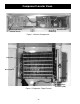
Defrost Heater Caution: Use care to avoid scratching the finish on unit walls. Styrofoam Insulation The defrost heater is a single calrod-type, radiant heater mounted on the evaporator. To remove the defrost heater: 1. Remove the evaporator fan (see Evaporator Fan procedure in the Airflow chapter). 2. Remove 8 screws and freezer ceiling panel. 3. Remove Styrofoam insulation from the bottom of the evaporator drain pan. 4. Loosen evaporator drain hose clamp. Evaporator Drain Pan 5.
Evaporator Thermistor The evaporator thermistor is mounted on the upper left side of the evaporator. The defrost cycle will terminate when the main control board detects 38 °F from the evaporator thermistor. The main control board must sense 38 °F in less than 35 minutes, or the defrost cycle will time out. Average time to defrost is less than 16 minutes. Defrost time should not exceed 35 minutes. Defrost time does not include dwell period.
Control System Touch Panel and Temperature Control Board Temperature Control Assembly The temperature control assembly is located at the top front of the fresh food compartment and contains the touch panel and temperature control board. The temperature control board receives switched DC voltage from the main control board. Input consists of pins 2 to 3. Failure of input results in default to most recent setting.
Pin 1 J9 Defrost Heater Pin 1 J11 Line Pin 1 J12 Monogram Drain Pan Heater – 25 – Pin 9 J7 Pin 8 Pin 7 Pin 6 Pin 5 Pin 4 Pin 3 Pin 2 Pin 1 Evaporator Fan Tach. Personality Input 5 Fan Common Evaporator Fan Condenser Fan FF Fan QuickChill Fan Fan +12V Neutral NIC FZ Door Switch FF Door Switch QuickChill Heater Auger Motor Interlock Water Valve Crusher Solenoid Auger Motor J2 Pin 1 Pin 2 Pin 3 Pin 4 Pin 5 Pin 6 Pin 7 Pin 8 Pin 1 QuickChill Htr. Pin 2 QuickChill Htr.
Main Control Board Locator Tables CONTROL BOARD PIN DEFINITIONS CONNECTOR PIN INPUT OUTPUT FUNCTION J1 1 VD C Feedback of fresh food thermistor value. Thermistor is NTC, when temperature drops, resistance value increases, causing return voltage reduction. This value is used to cycle fresh food fan (when used), evaporator fan, compressor, and condensor fan. Feedback is filtered to respond to 8 degrees of change per minute. J1 2 VD C Feedback of second fresh food thermistor value (when used).
CONTROL BOARD PIN DEFINITIONS CONNECTOR PIN INPUT OUTPUT FUNCTION J4 1 Digital Communication Digital Communication J4 2 VD C 12-VDC supply. J4 3 VD C DC common. Two-way digital communication between main control board, temperature control (board), dispenser board, and QuickChill board. CONTROL BOARD PIN DEFINITIONS CONNECTOR PIN INPUT OUTPUT FUNCTION J5 1 VD C 12 VDC to Climate Control Drawer damper when Express Chill (QuickChill) is selected.
CONTROL BOARD PIN DEFINITIONS CONNECTOR PIN J9 1 INPUT OUTPUT VAC FUNCTION Switched L1 voltage to the defrost circuit - 120 VAC. A timer counts how long this circuit is energized and uses this information to determine if the next defrost cycle is adaptive or nonadaptive. CONTROL BOARD PIN DEFINITIONS CONNECTOR PIN INPUT J11 1 VAC OUTPUT FUNCTION Constant L1 voltage to control board circuits - 120 VAC input potential for switched L1 terminals.
Main Control Board J7 Connector (120 VAC Side) Pin Wire Color Component Termination Input/ Output Pin-to-Pin Voltage Reading 1 Black Auger motor Output J7 pin 1 to J7 pin 9 = 120 VAC 2 Purple Crusher solenoid Output J7 pin 2 to J7 pin 9 = 120 VAC 3 Blue Water valve Output J7 pin 3 to J7 pin 9 = 120 VAC 4 Red Freezer door switch Input J7 pin 4 to J7 pin 9 = 120 VAC (FZ door closed) 5 Violet QuickChill Heater Output J7 pin 5 to J7 pin 9 = 120 VAC 6 Blue Fresh food door light sw
Main Control Board J4 Connector (Low -Voltage DC Side) Pin Wire Color Component Termination Input/Output Pin-to-Pin Voltage Reading 1 Red Temperature control Communication Two-way digital communication between main control board, temperature control (board), dispenser board, and QuickChill board. 2 Brown Temperature control VD C 12-VDC supply. 3 Orange Temperature control VD C DC common.
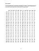
Thermistors This main control board uses input from 4 thermistors. These thermistors are located in the fresh food section, the freezer section, and on the evaporator. The main control board monitors the thermistors to determine the temperature in these areas of the unit and determines which components to run and when to run them based on this information. Thermistor Values Temperature Degrees (C) Temperature Degrees (F) Resistance in Kilo-ohms -40 -40 166.8 kΩ -30 -22 8 8 kΩ -20 -4 48.
Climate Control Drawer The Climate Control Drawer can chill or thaw items quickly. It can also store items at their optimum temperatures. This Climate Control Drawer contains the following components: • • • • • Control Board Thermistor Dampers (2) Fan Heater The main control board controls the dampers, fan, and heater based on input from the Climate Control Drawer’s control board and the thermistor.
Component Locator View Dampers Thermistor (in Fan Housing) Fan (in Fan Housing) Heater (in Fan Housing) Fan Connector 9-Pin Connector Air Diffuser Light Connector Heater Connector Top Panel (Mullion) Control Board (in Top Panel) Climate Control Drawer compartment shown with top panel moved out – 33 –
Operation During all modes of operation, the main control board will cycle the dampers, fan, and heater as necessary to maintain the desired temperature. Typical operation is as follows: Select Temp This feature maintains optimum temperatures for specific items. The CITRUS setting will maintain a drawer temperature of 43 °F by circulating warmed air or cooled air as needed. The dampers will close and the heater will turn on if warmed air is required to maintain 43 °F.
Temperature Table When using the Temperature Table, please note the following: • FF and FZ compartments should be within 3 °F of the temperature set point when checking drawer temperature. • All temperatures listed are as measured by the thermistor and displayed by the Climate Control Drawer display. • Actual drawer temperature will be displayed in Select Temp mode only.
Styrofoam Insert Climate Control Drawer Top Panel (Mullion) Removal Screws 1. Remove 2 storage bins and the glass panel over Climate Control Drawer. 2. Remove 4 screws from climate control top and slide back to access wire connectors. 3. Disconnect the connectors and remove the top panel. Top Panel (Mullion) Note: Note that there is a Styrofoam insert in the slot at the back, right-hand corner of the top panel.
Caution: When assembling the top panel, use care to prevent pinched wires. Troubleshooting Use this diagnostic flowchart if the Climate Control Drawer control panel and display are not operating properly. If the problem is drawer temperature and the control panel and display appear to be operating normally, check the thermistor, damper, fan, and heater first. If the actual drawer temperature displayed is incorrect, suspect the thermistor and main control board. Check communication using diagnostic mode.
Fan and Fan Housing The 12 VDC fan is controlled by the main control board. The main control board turns the fan on and off based on input from the Climate Control Drawer control board and thermistor. The fan should always come on any time Express Chill or Express Thaw is selected. Troubleshooting Turn on Express Chill. Check for 12 VDC at main control board between J2-8 and J2-7. NO 12 VDC present? Check communication using diagnostic mode. NO Communication pass? YES YES Replace main control board.
3. This step for fan removal only: Remove screen from front of fan and fan from housing. 9-Pin Connector Fan Connector 4. Remove 2 screws and the sheet metal cover from the right-hand side of the housing. 5. Disconnect fan connector. Screen and Fan 6. This step for fan removal only: Cut fan wires at fan to remove. Note: When installing new fan, fan wires do not have to be installed under plastic wire holders. Fan Housing Heater Connector 7. Disconnect heater connector and 9-pin connector. 8.
Heater The 120 VAC heater is located in the fan housing. The fan housing must be removed from the fresh food compartment to access the heater. The heater is controlled by the main control board. The main control board turns the heater on and off based on input from the Climate Control Drawer control board and the thermistor.
Access After removing the diffuser, the thermistor can be accessed through the hole on the right-hand side of the fan. After removing the thermistor from the clip (on the inside of the fan housing), the thermistor can be removed from the fan housing through the hole in the top of the housing. Thermistor shown removed from clip. Note: When installing the diffuser onto the fan housing, the tabs must be on the bottom and the flat surface must be on top.
Air Flow DAMPERS OPEN Shown with top panel and drawer removed. With the dampers open, cold air moves from the FZ compartment through the lower damper and into the fan housing. The fan blows the cold air through the diffuser into the drawer. The air returns from the drawer through the diffuser and into the fan housing. Air also moves over the top of the drawer, into the Climate Control Drawer compartment (not into the FF compartment), and then out of the compartment via the top damper.
Notes – 43 –
Compartment Lights The new Monogram side-by-side refrigerator uses 12 VAC halogen lights in both the fresh food and freezer compartments. The fresh food compartment is equipped with two 35-watt bulbs and five 20-watt bulbs producing a total of 170 watts. The freezer compartment is equipped with two 35-watt bulbs producing a total of 70 watts. Power is supplied to all interior lighting by 2 transformers. The transformers convert 120 VAC to 12 VAC.
Door Switches The fresh food and freezer door switches are located at the top of the fresh food and freezer compartments. The fresh food door switch closes when the door is open, providing L1 to the fresh food compartment light transformer. The freezer door switch is a dual-pole switch. It provides L1 to the main control board when the freezer door is closed. When the freezer door is open, the switch provides L1 to the freezer compartment light transformer.
Circuit Breakers Two resettable circuit breakers are located on the front of the transformer tray. Should a circuit breaker trip (open), it will open the transformer circuit it is associated with (freezer compartment or fresh food compartment), disabling that transformer and stopping voltage output to the interior lights. Transformers Transformers Power is supplied to all interior lighting by 2 transformers. One transformer is used for each compartment.
Type 1 Bulb Replacement WARNING: Halogen lights generate intense heat. Be certain power is off and lamps have sufficient time to cool before attempting to replace. 1. Set the master light switch to the OFF position and allow the lamps to cool. 2. To access the lamps in the fresh food compartment, remove the top pan. 3. Grasp each end of the curved light shield and pull the shield toward you to remove. 4. Remove the glass above the bulbs by pulling it straight out.
6. Turn the lamp protector to access the bulb. Note: Always follow bulb manufacturer’s directions for handling and replacing bulbs. 7. Remove the bulb by holding the base and pulling straight out. Replace with a new bulb and replace the lamp protector. WARNING: Lamp protectors must be replaced, or the heat from the bulb could damage the refrigerator. 8. Holding up the light housing, place each lamp assembly in its holder.
K 1330 ohms 39 ohms 330 ohms 39Ω CUBE 2Ω ICEMAKER WATER VALVE AUGER DISPENSER Schematic – 49 – Note: Climate Control Drawer is referred to as Quick Chill.
Refrigeration System The major components of the refrigeration system are a reciprocating-type compressor, condenser, condenser loop, dryer, and evaporator. These components, except for the condenser loop, are all replaceable separately. Compressor Heat Exchanger Suction Tube The compressor is a reciprocating type. Refer to the mini-manual for the BTU/hour rating and the compressor capacity test specification.
Dryer The dryer is positioned vertically in the center of the machine compartment. A copper process tube, connected to the inlet of the dryer, provides access to the high-pressure side of the refrigeration system. The capillary is connected to the outlet of the dryer. Replacement of filter dryer requires additional refrigerant when installed (0.5 oz). Process Tube Dryer Evaporator The evaporator is made of copper and aluminum and is located above the evaporator fan at the top of the freezer compartment.
Diagnostic Mode Enter the diagnostic mode by pressing both the freezer temperature pads (plus and minus) and the refrigerator temperature pads (plus and minus) simultaneously. All 4 pads must be held for approximately 3 seconds. Blinking “0’s” in both displays indicate the refrigerator has entered the test mode. Enter the appropriate display numbers as shown below and press any pad other than the temperature pads to activate that test mode.
Diagnostic Flowcharts Fresh Food Warm - Freezer Normal Check control settings and temperatures. Food at setting of 37 ˚F and 0 ˚F with no door openings for 12 hours should be: Fresh food 34 ˚F to 42 ˚F Freezer -8 ˚F to +6 ˚F Control settings require adjustment Adjust settings and allow 24 hours to stabilize. Control settings OK Basic refrigerator checks: Door gasket seal OK? Door switch - light turning off with door closed? NO Repair as necessary.
Fresh Food Too Cold - Freezer Normal Check control settings and temperatures. Food at a setting of 37 ˚F and 0 ˚F with no door openings for 12 hours should be: Fresh food 34 ˚F to 42 ˚F Freezer -8 ˚F to +6 ˚F Controls require adjustment Control settings OK Room temperature must be above 55 ˚F to avoid low ambient condition. NO Advise consumer of refrigeration installation requirements. Room temperature above 55 ˚F? YES Is the damper closed? NO Go to Damper Not Operating flowchart.
Fresh Food Warm - Freezer Warm Check control settings and temperatures. Food at setting of 37 ˚F and 0 ˚F with no door openings for 12 hours should be: Fresh food 34 ˚F to 42 ˚F Freezer -8 ˚F to +6 ˚F Control settings require adjustment Adjust settings and allow 24 hours to stabilize. Control settings OK Basic refrigerator checks: Door gasket seal OK? Door switch - light turning off with door closed? Repair as necessary.
Freezer Warm - Fresh Food Normal Check control settings and temperatures. Food at a setting of 37 ˚F and 0 ˚F with no door openings for 12 hours should be: Fresh food 34 ˚F to 42 ˚F. Freezer -8 ˚F to +6 ˚F. Control settings require adjustment. Adjust settings and allow 24 hours to stabilize. Control settings OK. Basic refrigerator checks: Door gasket seal OK? Door switch - light turning off with drawer closed? NO Repair as necessary.
Compressor Not Running Disconnect power. Warm freezer thermistor to 70 ˚F. Reconnect power and set controls to 37 ˚F and 0 ˚F. Is the compressor running? NO Check for 120 VAC at connector J7-9 orange wire to terminal J8 white wire. NO Replace main control board. Do you have 120 VAC? YES YES Adjust setting and allow 24 hours to stabilize. Direct-test the compressor. Did it start? YES Check wiring to compressor, overload, and relay. – 57 – NO Replace compressor.
Refrigerator Dead - No Sound, No Cooling Check house supply voltage. Are the interior lights on? NO House wiring problem. NO Are 120 VAC present? YES Check for 120 VAC at 3-pin connector at the rear of the unit. NO Repair or replace power cord. Are 120 VAC present? YES YES Repair wiring connections at 3-pin connector. Unplug J2 connector from main control board. Check for 12 VDC at control board pins J2-3 to J2-8. NO Unplug J4 connector from main control board.
Damper Door Does Not Operate Remove blockage or replace damper. Push on damper door to check manual movement. YES Is the damper door stuck? NO Push damper door halfway closed. Unplug refrigerator to reset main control board. Set temperature controls to 37 ˚F and 0 ˚F. Reconnect power. Replace main control board. YES Verify thermistors are within proper range using thermistor values chart. Does damper door move immediately after reconnecting power? (You have 10 seconds to check.
Heavy Frost on Evaporator Always check door ajar, customer usage numerous door openings, etc. Disconnect power. Unplug blue connector from main board. Measure between red wire on connector and orange (neutral) wire on main board J7, pin 9. Are there approximately 37 ohms? YES Verify thermistors are within proper range using thermistor values chart. Is resistance within range? YES NO Replace main board. Check wiring harness, defrost heater, and defrost overtemperature thermostat.
Evaporator Fan Not Running Always check fan for obstruction first. Disconnect power to reset main control board. Warm freezer thermistor to 70 ˚F. Set temperature controls to 37 ˚F and 0 ˚F. Reconnect power. At the evaporator fan connector, check for 13 VDC from the red to white wire and 8-13 VDC from the yellow to white wire. NO Unplug J2 connector on the main control board. Check for 13 VDC between pins J2-8 and J2-3 and 8-13 VDC between pins J2-4 and J2-3.
Condenser Fan Not Running Always check for obstruction first. Disconnect power to reset main control board. Warm freezer thermistor to 70 ˚F and set temperature controls to 37 ˚F and 0 ˚F. Reconnect power. At the condenser fan connector, check for 13 VDC from the red to white wire and 11-13 VDC from the pink to white wire. Is the voltage correct for both? NO Unplug J2 connector on the main control board. Check for 13 VDC between pins J2-3 and J2-8 and 11-13 VDC between pins J2-3 and J2-5.
Warranty YOUR MONOGRAM REFRIGERATOR WARRANTY Staple sales slip or cancelled check here. Proof of original purchase date is needed to obtain service under warranty. WHAT IS COVERED From the Date of the Original Purchase FULL TWO-YEAR WARRANTY For two years from date of original purchase, we will provide, free of charge, parts and service labor in your home to repair or replace any part of the refrigerator that fails because of a manufacturing defect.
Notes – 64 –
Notes – 65 –
Notes – 66 –
Notes – 67 –
Notes – 68 –
Notes – 69 –
– 70 –