Installation Instructions If you have questions, call 800.GE.CARES or visit our website at: monogram.
Safety Information READ AND SAVE THESE INSTRUCTIONS BEFORE YOU BEGIN Read these instructions completely and carefully. • IMPORTANT ³ Save these instructions for local inspector’s use. • IMPORTANT ³ Observe all governing codes and ordinances. • Note to Installer ³ Be sure to leave these instructions with the Consumer. • Note to Consumer ³ Keep these instructions with your Owner’s Manual for future reference. • Skill Level ³ Installation of this appliance requires basic mechanical and electrical skills.
Consignes de Sécurité LISEZ ET CONSERVEZ CES INSTRUCTIONS AVANT DE COMMENCER Lisez ces instructions entièrement et attentivement. IMPORTANT • ³ Conservez ces instructions pour l’inspecteur électrique local. • IMPORTANT ³ Respectez tous les codes et règlements en vigueur. • Remarque pour l’installateur – Assurez–vous de remettre ces instructions à l’utilisateur. • Remarque pour l’Utilisateur – Conservez ces instructions avec votre notice d’utilisation pour toute référence future.
Design Information CONTENTS Design Information Product Dimensions ............................................................................ 4 Duct Cover Accessories ..................................................................... 5 Product Clearances ............................................................................. 5 Advance Planning Ductwork Planning ............................................................................. 6 Ceiling Framing for Support ..............................
Design Information PRODUCT CLEARANCES DUCT COVER ACCESSORIES *Height to Ceiling 20" For ZV42I 24" For ZV54I 30" Min. 36" Max. 36" Min. =9 , * 9” for ceiling heights 7’11” to 8’5” using the supplied support frame and duct cover. 2UGHU =; '& for ceiling heights of 8”6” to 10’4”. =9 , * 5” for ceiling heights 7’11” to 8’5” using the supplied support frame and duct cover. 2UGHU =; '& for ceiling heights of 8”6” to 10’4”. These accessories include telescoping support frames and decorative covers.
Advance Planning ADVANCE PLANNING Ductwork Planning • These vent hoods are equipped for 10” round ductwork. • Determine the exact location of the vent hood. • Plan the route for venting exhaust to the outdoors. • Use the shortest and straightest duct route possible. For satisfactory performance, duct run should not exceed 150 ft. equivalent length for any duct configurations. • Refer to “Duct Fittings” chart to compute the maximum permissible length for duct runs to the outdoors.
Advance Planning INSTALLATION HEIGHT REQUIREMENTS • These vent hoods must be installed 30” min. and 36” max. above the cooking surface – regardless of the ceiling height. Therefore, installation height of the hood depends on the exact ceiling height of the kitchen. • Accessories are available for ceiling heights 8’6” and up to 10’4”. Example: Hood installation height with 8 ft. ceilings. 8 ft. Ceiling 8 ft.
Advance Planning DUCT FITTINGS Use this chart to compute maximum permissible lengths for duct runs to outdoors. For best results, use 10” diameter duct. Note: Do not exceed maximum permissible equivalent lengths! Maximum recommended duct length IRU WKHVH KRRGV IHHW Flexible ducting: If flexible metal ducting is used, all the equivalent feet values in the table should be doubled. The flexible metal duct should be straight and smooth and extended as much as possible.
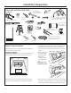
Installation Preparation TOOLS AND MATERIALS REQUIRED 7/16” Pivoting hex socket with 4” and 6” extensions (NOT SUPPLIED) Duct tape Pencil and tape measure Wire cutter/ stripper Hammer Key Hole Saw Electric or battery operated drill and 3/16”, bits, Phillips and Flat Blade Screwdriver bits. 10” round metal duct, length to suit installation. Safety glasses Wire nuts Spirit level Flashlight Saber saw or Sawsall Step ladder Phillips and flat blade screwdrivers Strain relief for junction cover.
Installation Preparation PARTS PROVIDED Locate the parts packed with the hood. Allen Wrench Transition with Damper Support frame for 8 ft. ceiling with 4 large pan head screws installed on the bottom corners. Implement rods with standoffs 2-piece decorative duct cover Duct collar Decorative top cover 2 Filters (3 with 54” hood) 2 Grease trays (3 with 54” hood) HARDWARE PACKAGE ACCESSORY PACKAGE Locate and check contents. Screws shown actual size.
Installation Instructions 67(3 & 216758&7 &(,/,1* 6833257 Plan the Location of the Hood and Ductwork • Use a plumb bob to check the location. The countertop/cooktop below the hood must be centered with the hood. • The hood should extend beyond the front and rear edge of the cooking appliance. • The duct in the ceiling must be centered over the cooktop.
Installation Instructions 67(3 & 216758&7 &(,/,1* 6833257 CONTINUED 12-3/4” (42” Hood) 17” (54” Hood) Install Cross-Framing Symmetrically About Duct/ Cooktop Centerline EXAMPLE B 16” Joist Spacing 8 5/8” 2x4 Cross Framing µ 'XFW Front of Hood Align duct to center of Cooktop Cooktop Outline Top View – Ceiling Joists Run Perpendicular to Front of Hood EXAMPLE C 12-3/4” (42” Hood) 17” (54” Hood) Install Cross-Framing Symmetrically About Duct/Cooktop Centerline 2x4 Cross Framing 8 5/8” µ '
Installation Instructions 67(3 & 216758&7 &(,/,1* 6833257 CONTINUED • Secure each 2 x 4 block with at least four (4), #10 wood screws, 3” long (not supplied). Use 8 wood screws total for the two supports. 2x 4 Min. Cross Framing • The cross framing must be accurately aligned to assure correct positioning of the hood. • The cross framing must be level in all directions. Check with a spirit level and adjust if necessary.
Installation Instructions 67(3 0 2817 7(03/$7( • Select the template for your hood size. • Align the template with the marks on the ceiling and tape in place. – Be sure the template is oriented correctly, with the front of the hood. • Use a plumb to check to be sure the mounting holes will provide parallel alignment with the countertop below. • Center punch all hole locations. • Drill pilot holes in the 4 screw locations. Use a 3/16” bit and drill approximately 1-1/2” deep.
Installation Instructions 67(3 I NSTALL ACCESSORY (OR SUPPLIED) SUPPORT AND DUCT COVERS Install Small Pan Hea Screws on Each Side Top Duct Cover Install Safety Screw on Each Side Adjust Frame to nstallation Height Bottom Duct Cover Install Stop Screw Screws E Install supplied support frame OR telescoping accessory frame • Hang the supplied support frame or telescoping accessory frame to the ceiling joists and cross framing on the 4 hex head screws by engaging the keyhole slots on the frame.
Installation Instructions 67(3 , 167$// '8&7 75$16,7,21 WITH DAMPER 67(3 INSTALL HOOD Note: THREE PEOPLE ARE REQUIRED TO COMPLETE THIS INSTALLATION! Bumper Pads Duct Transition 1/4" Gap Attachment Keyholes Attachment Screws Screws C IMPORTANT: Remove shipping tape from damper and check that damper moves freely. • Place the transition piece over the hood exhaust and secure with 4 Screws C provided. • Use duct tape to seal the connection. Check to be sure the damper moves freely.
Installation Instructions 67(3 CONNECT ELECTRICAL Verify that power is turned off at the source. WARNING: If house wiring is not 2-wire with a ground wire, a ground must be provided by the installer. When house wiring is aluminum, be sure to use UL approved anti-oxidant compound and aluminum-to-copper connectors. • Install strain relief onto the knockout of the junction box. • Insert house wiring through strain relief and tighten.
Installation Instructions 67(3 6 /,'( '8&7 &29(5 '2:1 67(3 INSTALL RODS SKIP THIS STEP IF USING THE SUPPLIED DUCT COVER • Use a flat blade screwdriver to install stand-offs into the bottom of the hood. • Align implement rod to stand-offs with the screw hole towards the inside of the hood. Secure the rod to the stand-offs with the supplied Allen wrench. • Follow the same procedure on the opposite side. • Hold the duct cover in place and remove the temporary stop screw.
Installation Instructions 67(3 INSTALL SUPPLIED DUCT COVER AND TOP COVER 67(3 INSTALLATION CHECKLIST Install Duct Cover Screw on Each Side Screws D • Install the supplied 2-piece duct cover over the support frame (if using supplied frame). Snap ends together. • Secure duct covers to support frame with 2 Screws D. • For a more finished appearance, a top cover is supplied and should be installed whenever the top of the hood is visible.
Note: While performing installations described in this book, safety glasses or goggles should be worn. For Monogram® local service in your area, call 1.800.444.1845. Note: Product improvement is a continuing endeavor at General Electric. Therefore, materials, appearance and specifications are subject to change without notice. 49-80209-5 02-13 GE Printed in Mexico GE Appliances & Lighting Appliances General Electric Company Louisville, KY 40225 GEAppliances.