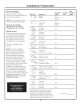
Installation Instructions Tou have questions, doll Sottish 2000 Sst oA Ebert Sh A ROCKEFELLER LL | 36" Chimney Vent Hood 2800 01-13 GE monogram.
Safety Information BEFORE YOU BEGIN Read these instructions completely and carefully. RANT — Save these instructions for local inspector's use . IMPORTANT Observe all governing codes and ordinances. « Note to installer — Be sure to leave these instructions with the Consumer. « Note to Consumer — Keep these instructions with your Owner's Manual for future reference. « Skill Level — installation of this appliance requires basic mechanical and electrical skills, « Completion Time Hours.
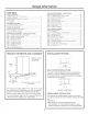
Design Information CONTENTS Design Information Product Dimensions and Clearances . installation Options Advance Planning, Du Bower Supply. Duct Fittings. Installation Preparation Tools and Materials Required. Remove the Packaging. ps Mount installations... installation Below Wall Cabinet Check Installation Hardware Duct work, Wiring Locations... Wall-Mounted Installation ~ Vented to the Outside Step 1, Install Framing for Hood Support. Step 2, Install Mounting Bracket. . Step 3.
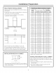
Installation Preparation ADVANCE PLANNING = Determine the exact location of the vent hood. » Plan the route for venting exhaust to the outdoors. + Use the shortest and straightest duct route possible. For satisfactory performance, duct run should not exceed 100 ft. equivalent length for any duct configurations. « Refer to "Duct Fittings” chart to compute the maximum permissible length for duct runs to the outdoors.
Installation Preparation DUCT FITTINGS Use this chart to compute maximum permissible lengths for duct runs to outdoors. NOTE: Do not exceed maximum permissible equivalent lengths! Maximum duct length: 100 foot for 6” round duct 75 foot for x 12“ duct Flexible ducting: If flexible metal ducting is used, all the equivalent feet values in the table should be doubled. The flexible metal duct should be straight ond smooth and extended os much as possible DO NOT use flexible plastic ducting.
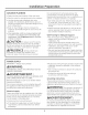
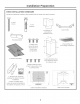
Installation Preparation TOOLS AND MATERIALS REQUIRED {NOT SUPPLIED) # Tape measure ® Rife # Spirit level ® Wire cutter/stripper # Wire nuts # Electric drill with 1/8” and 3/8" bits # Phillips and flat blade screwdrivers # Hammer # Pliers # Softy glasses # Duct tape # Tape te mount template # Gloves to protect against sharp edges # 120V BO Hz.
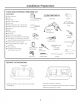
Installation Preparation WALL MOUNT INSTALLATIONS These hoods may be installed onto a wall or below a wall cabinet. *» Telescopic duct covers are provided to conceal the duct work, running to the ceiling. + This hood can be installed for recirculating operation. No kits required.
Installation Preparation CHECK INSTALLATION HARDWARE Locate the hardware accessory box packed with the hood and check contents.
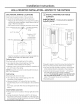
Installation Instructions WALL-MOUNTED INSTALLATION-VENTED TO THE OUTSIDE DUCT WORK, WIRING LOCATIONS Determine the exact location of the vent hood. « Locate the plotter packed with the literature, ~ Measure 36” from the floor to the top of the cooking surface. Add hood installation height determined on page 7. Mark that location ~Use a level to draw a straight pencil line on the wall. 3-374" center line to will = ge for ceiling vent ducting i Ceiling dio. hole Center line min.
Installation Instructions WALL-MOUNTED INSTALLATION-VENTED TO THE OUTSIDE INSTALL MOUNTING BRACKET This vent hood must be secured to the horizontal support or wall studs. » With the template taped in place, use o punch to mark all mounting screw locations « Drill 1/8” pilot holes at the 6 punched locations, » Remove the template « The 2 holes in the support bracket holes must enter studs or the horizontal support. Use wood screws to secure the mounting bracket to the wall.
Installation Instructions WALL-MOUNTED INSTALLATION-VENTED TO THE OUTSIDE PREPARE THE HOOD + Remove the hood from the box. Remove packaging and tape.
Installation Instructions WALL-MOUNTED INSTALLATION-VENTED TO THE OUTSIDE [6] CONNECT DUCT WORK Air flow + Install duct work, miking connections in direction of airflow as illustrated + Push duct over the exhaust outlet and damper. Duct tape Secure joints in duct work with sheet metal screws over seam « Wrap all duct joints with duct tape for on airtight ond screw seal. « Use duct type to seal the flung connections, Screw CAUTION: Do not use sheet metal screws at the hood flange connection.
Installation Instructions WALL-MOUNTED INSTALLATION-VENTED TO THE OUTSIDE INSTALL DUCT COVERS * Place the decorative duct covers on top of the hood. Mounting NOTE: The inside {upper} screws duct piece has holes on one end. The holes are intended for use when the hood is installed for recirculating purposes.
Installation Instructions WALL-MOUNTED INSTALLATION—RECIRCULATING DUCT WORK, WIRING LOCATIONS « Determine the exact location of the vent hood. » Locate the template packed with the literature. » Measure 36" from the floor to the top of the cooking surface. Add hood installation height determined on page 7. Mark that location. = Ceiling § * Tape the template in position along the penciled line. CHECK TO BE SURE THE TEMPLATE IS LEVEL.
Installation Instructions WALL-MOUNTED INSTALLATION—RECIRCULATING INSTALL MOUNTING BRACKET This vent hood must be secured to the horizontal support or wall studs. « With the template taped in place, use 0 punch to mark alt mounting screw locations. « Drill 1/8” pilot holes at the 6 punched locations * Remove the template. « The 2 holes in the support bracket holes must enter studs or the horizontal support. Use wood screws to secure the mounting bracket to the wall.
Installation Instructions WALL-MOUNTED INSTALLATION—RECIRCULATING MOUNT THE HOOD Install a wood screw on each side of the taunting farm —em Mounting bracket » Lift the hood onto the mounting bracket # Check to be sure iris level, » Install wood screws through the hood and into the wall on each side of the mounting bracket. Install bottom mounting Screws « Extend the canopy forward for better access to the rear mounting screw holes.
Installation Instructions WALL-MOUNTED INSTALLATION—RECIRCULATING [6] CONNECT ELECTRICAL Verify that power is turned off ot the source. WARN ] NG: If house wiring is not 2-wire with a ground wire, a ground must be provided by the installer. When house wiring is aluminum, be sure to use U.L. approved anti-oxidant compound and aluminum-to-copper connectors. ADVERTISEMENT Silas mason n'est pas cable ave deluxe filch et un fil de terr, installation dot installer un fit de terr.
Installation Instructions WALL-MOUNTED INSTALLATION—RECIRCULATING INSTALL FILTERS Charcoal filter * Remove protective film on the filters. + Install the black charcoal filter into the center opening. Metal grease filters = Tip filters into the slots ot the rear of the opening. Lift the filter lock and pull forward until the filter rests in the slots.
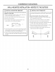
Installation Instructions UNDER-CABINET INSTALLATION CABINET REQUIREMENTS This hood may be installed beneath a wall-mounted cabinet. «If the cabinet has been installed, it must be removed so that wall framing supports can be dded. 207 Min. X 24° Min, The cabinet must be ot least 20” high between the bottom frame and the inside top.
Installation Instructions UNDER-CABINET INSTALLATION INSTALL FRAMING FOR HOOD SUPPORT IMPORTANT: Framing must be capable of supporting 100 ibs. View from rear cleats 17% 6 rin. routing Center line of installation space L— if drywall is present, mark the screw hole locations for the top mounting brackets. Remove the template, « Cut away enough drywall to expose 2 vertical studs at the bracket location indicated on the template.
Installation Instructions UNDER-CABINET INSTALLATION CUT THE OPENING if the cabinet has been installed, remove it from the wall. » Use the Top Cabinet Template to locate and cut a hole in the bot torn of the cabinet.
Installation Instructions UNDER-CABINET INSTALLATION [6] MOUNT THE HOOD Install a wood screw on each side of the mounting frame » Carefully, lift the hood into the cabinet. Guide the hood upwards to meet the duct work. IMPORTANT: One person must hold the hood in place while the other drives the screws into the mounting frame. 22 COMPLETE THE INSTALLATION AND CONNECT DUCT WORK Install 2 Screws into Each Side Bracket » Drive 2 screws into each side bracket.
Installation Instructions UNDER-CABINET INSTALLATION CONNECT ELECTRICAL WARNING: house wiring is not 2-wire with a ground wire, a ground must be provided by the installer. When house wiring is aluminum, be sure to use U.L. approved anti-oxidant compound and aluminum-to-copper connectors. ADVERTISEMENT : Silas mason n'est pos cable ave deluxe filch et un fil de terr, Installation dot installer un fil de terr.