Installation Instructions ZV950 36" Stainless Steel Vent Hood
Safer information BEFORE YOU BEGIN Read these instructions completely • IMPORTANTfor local inspector's WARNING" [] TO REDUCE THE RISK OF FIRE, ELECTRICAL SHOCK OR INJURY TO PERSONS, OBSERVE THE FOLLOWING: A. Use this unit only in the manner intended by the manuf_mmrer. If you have any questions, contact the manufacturer. B.
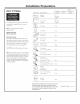
Desi n information CONTENTS Design Information Product Dimensions and Optional ......................................................... Accessories Installation Advance Clearances ........................... Ductwork, Wiring i,ocations ............................................. Installation Instructions 3-4 4 Step Planning, Ductwork, Step Framing 5 Step Power Supp b, ..................................................................... 5 Step Duct Fittings ...........................
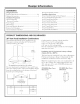
Desi n information PRODUCT DiMENSiONS CLEARANCES (cont.) AND OPTIONAL ZX14SDSS, is available Using Duct Cover Accessories A Duct Cover Accessory may and be reqtfired for yore hood installation height. Use this chart to determine installation height and accessory for your ceiling height. ZV950SDSSInstallationHeights * Possible Hood installation Height 7' 11" 24-I/2" up to 14 fL the optional duct cover at the same time vent hood and have on site beff_re installation. Note: Duct book.
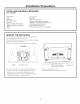
installation Preparation ADVANCE PLANNING Ductwork Planning * Determine the exact • Use location of the vent hood. * Plan the route for venting exhaust to the outdoors. e Use the shortest and straightest duct route possible. For satisfacto W performance, duct run should not exceed lO0 equivalent length for any duct configurations. * Refer to "Duct Fittings" chart to compute the maximum permissible length for duct runs to the outdoors. duct_,vork.
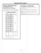
installation Preparation DUCT FiTTiNGS Duct Piece Equivalent Length* Dimensions Quantib_ Used Total Equivalent Length IIL straight Round, (per foot length) lft. Use this permissible chart to compute lengths for 3-1/4" x 12" straight maxhnmn duct runs (per foot length) to O tltdooYs. 17 ft. (_ 90 ° elbow (_ 45 ° elbo_a 10ft. 90 ° elbo_ 3-1/4" x 12" 43 ft. 3-1/4" x 12" 45 ° elbox_ 26 ft. Note: Do not exceed maximum ?ermissible equivalent lengths! Maximum duct length: 100 ft.
installation Preparation TOOLS AND MATERIALS REQUIRED {NOT SUPPLIEDI . Tapemeasure Knife Spirit level Wire cutter/stripper Wire nuts Electric drill with 1/8"and 3/8" bits Phillips and flat blade screwdrivers . Hammer . Pliers . Safety glasses . Duct tape .Tape to mount template . Gloves to protect against sharp edges .120V 60Hz. 15 or 20 Amp, 2 wire with ground. Properly grounded branch circuit. . Strain relief for junction cover. .8" round metal duct, length to suit installation.
installation Preparation CHECK iNSTALLATiON i,ocate the hardware accessory hood and check contents. HARDWARE box packed with the DUCTWORK, WIRING Determine locadon the exact * i,ocate the template packed with the literature. - Measure 36" from the floor to the top of the cooking smfhce. Add 25-1/2" (or other recommended space) f)om the cooking surface to the bottonl of the hood. Mark that location. - Use a level to draw 8 Wood Screws LOCATIONS of the vent hood.
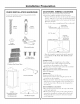
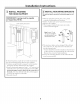
installation instructions iNSTALL MOUNTING iNSTALL FRAMING FOR HOOD SUPPORT This vent hood must he secured to the horizontal support or wall studs. • With i of IMPORTANT: supporting Framing 100 Ibs. must BRACKETS be capable the to mark • Drill 1/8" • Remove 8"Min.
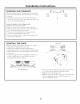
Installation instructions iNSTALL DUCT BRACKET The duct This bracket at the bracket will must hold be installed the decorative against the duct cover ceiling. Pre-Tap I Side ' Screw in place top. * Install bracket. the 2 small Remove screws the into screws. the sides of the Pre-tapping the I I I Pie-Tap 'Side Screw duct holes will insme ease of final installation. Secure the bracket to the ceiling and wall: * Mark tile 4 screw hole locations.
Installation instructions CONNECT DUCTWORK . Install ductwork, making connections of airflow as illustrated. * Push duct over the exhaust outlet until in direction DuctTape it reaches Over Seam the duct stops. * Secmejoints in ductwork with sheetmetal screws. * Wrap all duct joints with duct rope for an airtight seal. * Use duct tape to seal the flange connection. W ii CAUTION" []Do not use sheet metal screws at the hood flange connection. Doing so will prevent proper damper operations.