Installation Instructions Downdraft PVB94 PVB98 ZVB30 ZVB36 Vent Systems
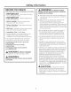
Safet Information BEFORE YOU BEGIN Read these instructions completelg A WA R N IN G:TOREDUCE THE RISK and carefullg. " IMPORTANT- Save these instructions for local inspector's use. "IM PORTANT- Observe all governing codes and ordinances. , Note to Installer- Be sureto leavethese instructions withthe consumer. , Note to Consumer for future reference. - Keep these instructions , Skill Level- Installation of these vents require basic mechanical and electrical skills. , Completion Time- 1to 3 hours. .
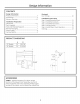
CONTENTS Design Information Product Dimensions ................................................................ 3 Accessories .................................................................................. 3 Advance Planning ............................................................... 4, 5 Installation Preparation Clearances .............................................................................. 6, 7 Parts Supplied ............................................................................
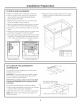
Desi n Information ADVANCE PLANNING Downdraft Vent and Cooktop Cutout The installation of these downdraft vents with ang GE or Monogram cooktop requires careful consideration. Before you begin, review the combination cutout illustrations on page 6. Before gou must: 1. Review countertop dimension illustrations sure gou will have enough flat countertop to be surface. 2.
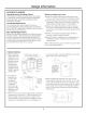
Desi n Information Clearances Electrical and Gas Locations , The downdraft system with blower, motor and ductwork will occupy the cabinet below the countertop and cooktop. Plan the placement of the electrical outlet and gas connections (if used) carefully. Electrical outlets and gas connections cannot be placed on the back wall of the cabinet because it may interfere with the downdraft plenum. Refer to POWER SUPPLY section for information on location of electrical and gas connections.
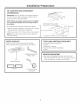
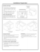
Installation Preparation CUTOUTS AND CLEARANCES , Measure carefullg when cutting the countertop. , Make sure sides of the opening are parallel and rear and front cuts are exactlg perpendicular (right angles) to the sides. o Measure the base cabinet width at the top and bottom to ensure it meets the minimum width requirements. , Measure to be sure there is room for clearances to the front edge of the countertop.
Installation Preparation 36" COOKTOP AND DOWNDRAFT COMBINATION 8-!/2" IMPORTANT: The countertop cutout depth requires 23-i/2" minimum flat countertop surface and 25" minimum total countertop depth. NOTE: Before you begin, measure and mark depth to ensure that adequate fiat countertop surface isavailable.
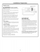
Installation Preparation POWER SUPPLY Locate the Gas or Electrical Connection Onlg Within the Shaded Area A WARNING: SHOCK HAZARD FOR PERSONAL SAFETY,THIS APPLIANCE MUST BE PROPERLYGROUNDED. / / 9- Remove house fuse or open circuit breaker before beginning installation. I J ' 1/2 " Gas or Electrical Connections within this Area 34" for DO 36" NOT Models Locate 28-1/2" for 30" Models Electrical Outlet 12" Do not use an extension cord or adapter plug with this appliance.
Installation Preparation VENTING OPTIONS Loosen Screws to Adjust 3-1/2" to Left or Right , The downdraft vent is shipped with the discharge outlet pointing straight down and can be changed to the left or right side. • The blower outlet is sized for 3-1/4" x 10" and can be transitioned to 6" round. • Order JXRB67 for installation of the blower and motor below the floor. Side-to-Side Adjustments: The entire blower mounting plate can be adjusted 3-1/2" to the left or right.
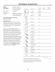
Installation Preparation DUCT FITTINGS Use 3-1/4" x 10" duct. It can transition to 6" round. Downdraft equivalent Use this chart to compute maximum permissible lengths for duct runs to outdoors. Total Equivalent Duct Piece Flexible ducting: If flexible metal ducting is used, all the equivalent feet values in the table should be doubled. The flexible metal duct should be straight and smooth and extended as much as possible. DO NOT use flexible plastic ducting.
Installation [] INSTALL DOWNDRAFT Instructions VENT (_) Two stabilizing brackets must be installed on each side of the downdraft vent. , For right-side or straight-down discharge, fasten the stabilizing locations A, B, D and E. blower brackets at . For left-side blower discharge, stabilizing brackets at locations fasten the B, C, D and E. L_w i .................. --E Dj A_ C_ O Place Cooktop into the countertop cutout.
Installation [] Instructions INSTALL REMOTE SWITCH AWARNING: SHOCK HAZARD Connect Remote Switch to Remote Harness • Thread the remote harness through the 1/2"-dia. hole and attach the harness connector to the remote connector. Disconnect electrical power from unit before beginning switch installation. Failure to do so could result in personal injurg or damage to the electrical controls.
Installation instructions r4-] CONNECT POWER Plug power cord into properlg grounded receptacle. rs] INSTALL FILTERS, CHECK OPERATION • Press the ON/OFF pad on the control to raise the vent. • Slip fingers into the vent holes. Lift the vent straight up and pull forward. Retainers Filter Tabs • Slide filter into the retainers Grid close the vent. o Press the Fan Speed HIGHER pad to start the blower. Adjust the blower bg pressing HIGHER or LOWER. , To lower the vent, press the ON/OFF pad.
Notes 14
Notes 15
NOTE:While performing installations described in this book, safety glasses or goggles should be worn. NOTE:Product improvement is a continuing endeavor at Genera] Electric. Therefore, materials, appearance and specifications are subject to change without notice. 131-i0728-7 01-13 GE ] GE Consumer & Industrlel Appliances General Electric Comp(]ny Louisville, K¥ 40225 GEApplionces.