D 6 7 8 9 10 11 12 13 1 2 3 4 GB 5 F E GEA Bock Compressor HG22e A 96192-11.
About these instructions Read these instructions before assembly and before using the compressor. This will avoid misunderstandings and prevent damage. Improper assembly and use of the compressor can result in serious or fatal injury. Observe the safety instructions contained in these instructions. These instructions must be passed onto the end customer along with the unit in which the compressor is installed.
96192-11.2014-DGbFE Contents 1 1.1 1.2 1.3 1.4 2 2.1 2.2 2.3 3 3.1 3.2 3.3 4 4.1 4.2 4.3 4.4 4.5 4.6 4.7 4.8 5 5.1 5.2 5.3 5.4 5.5 5.6 5.7 6 6.1 6.2 6.3 6.4 6.5 6.6 6.7 7 7.1 7.2 7.3 7.4 7.5 7.
1| Safety 1.1 Identification of safety instructions: DANGER! Indicates a dangerous situation which, if not avoided, will cause immediate fatal or serious injury. WARNING! Indicates a dangerous situation which, if not avoided, may cause fatal or serious injury. CAUTION! Indicates a dangerous situation which, if not avoided, may cause fairly severe or minor injury. ATTENTION! Indicates a situation which, if not avoided, may cause property damage.
1| Safety 1.4 Intended use These assembly instructions describe the standard version of the HG22e A manufactured by GEA Bock. The compressor is intended for use in refrigeration systems in compliance with the limits of application. Only the refrigerant specified in these instructions may be used.
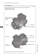
2| Product description 2.1 Short description • Semi-hermetic two-cylinder reciprocating compressor with oil pump lubrication. • Lightweight aluminum design • Suction gas cooled drive motor Transport eyelet Discharge shutoff valve 6 Oil pump D 1 2 7 8 9 10 11 12 13 Name plate 3 4 5 Oil sight glass GB F Fig. 1 E Cylinder cover Terminal box Valve plate Motor section Suction shut-off valve Fig. 2 Dimension and connection values can be found in Chapter 9 6 96192-11.
2| Product description 2.2 NameTypschild plate (example) (Beispiel) GEA Bock GmbH 72636 Frickenhausen, Germany 1 2 3 4 5 1 21 32 43 4 5 5 6 7 8 9 10 11 12 13 HGX22e/190-4 S A AS35830A001 16,2/9,4A 87A 50A 66 Fig. 3 Typbezeichnung Type designation Maschinennummer Machine number maximaler Betriebsstrom maximum operating current Anlaufstrom (Rotor blockiert) Starting current (rotor blocked) ND (LP): max. zulässiger Stillstandsdruck ND (LP): max.
3| Areas of application 3.1 Refrigerants • HFKW / HFC: • (H)FCKW / (H)CFC: R134a, R404A/R507, R407C R22 3.2 Oil charge The compressors are filled at the factory with the following oil type: - for R134a, R404A/R507, R407C FUCHS Reniso Triton SE 55 - for R22 FUCHS Reniso SP 46 Compressors with ester oil charge (FUCHS Reniso Triton SE 55) are marked with an X in the type designation (e.g. HGX22e/190-4 A). ATTENTION! D GB F E For refilling, we recommend the above oil types.
R134a Fig. 5 R407C D Unlimited application range Fig. 6 GB Supplementary cooling or reduced suction gas temperature Supplementary cooling and reduced suction gas temperature Motor version S (more powerful motor) R404A/R507 Evaporating temperature (°C) Condensing temperature (°C) Suction gas superheat (K) Suction gas temperature (°C) Fig. 7 96192-11.2014-DGbFE Max. permissible operating pressure (LP/HP)1): 19/28 bar 1) R22 Fig.
4 | Compressor assembly INFO! New compressors are factory-filled with inert gas (3 bar nitrogen). Leave this service charge in the compressor for as long as possible and prevent the ingress of air. Check the compressor for transport damage before starting any work. 4.1 Storage and transport Fig. 9 ? Storage at (-30°C) - (+70°C), maximum permissible relative humidity 10% - 95%, no condensation Do not store in a corrosive, dusty, vaporous atmosphere or in a combustible environment. Use transport eyelet.
4 | Compressor assembly 4.3 Maximum permissible inclination ATTENTION! Poor lubrication can damage the compressor. Respect the stated values. A A a a Fig. 14 A A a a A max. 30°, max. 2 minutes a max. 15°, continuous operation 4.4 Pipe connections Fig. 15: Stepped internal diameters The discharge and suction line valves have stepped internal diameters so that pipes with standard millimetre and inch dimensions can be used. The depth of pipe insertion will depend on the dimension.
4 | Compressor assembly 4.5 Pipes Pipes and system components must be clean and dry inside and free of scale, swarf and layers of rust and phosphate. Only use air-tight parts. Lay pipes correctly. Suitable vibration compensators must be provided to prevent pipes being cracked and broken by severe vibrations. Ensure a proper oil return. Keep pressure losses to an absolute minimum. 4.
4 | Compressor assembly 4.7 Operating the shut-off valves Before opening or closing the shut-off valve, release the adjustable valve spindle seal by approx. ¼ of a turn counter-clockwise. After activating the shut-off valve, re-tighten the adjustable valve spindle seal clockwise. Release Valve spindle seal Tighten Fig. 18 Fig. 17 4.
5| Electrical connection 5 Electrical connection DANGER! INFO! High voltage! Risk of electric shock! Only carry out work when the electrical system is disconnected from the power supply! onnect the compressor motor in accordance with the circuit diagram C (see inside of terminal box). Use suitable cable entry point of the correct protection type (see name plate) for routing cables into the terminal box. Insert the strain reliefs and prevent chafe marks on the cables.
5| Electrical connection The compressor is designed with a motor for star-delta circuits. Designation on the name plate Sticker on the terminal box Niedere Spannung Low voltage Bas voltage ∆ ∆/Y Star-delta start-up is only possible in the ∆ voltage range.
5.
A1 Alarm Motor protection A2 Overheating R1, R2 A3 Alarm high pressure XSS Terminal strip in the external switch cabinet D GB F E 96192-11.
5| Electrical connection 5.4 Electronic trigger unit MP 10 The compressor motor is fitted with cold conductor temperature sensors (PTC) connected to the electronic trigger unit MP 10 in the terminal box. Readiness to operate is signaled by the H3 LED (green) after the power supply is applied. In case of excess temperature in the motor winding, the unit switches off the compressor and the H1 LED illuminates red.
5 | Electrical connection 5.6 External connection of the MP 10 for terminal boxes at reduced height (Accessories) 0,5 mm² X3: 2 1 PTC1 PE 3 3 4 4 PTC2 Terminal box Fig. 23 R2 D 5.7 Function test of the trigger unit MP 10 GB Before start-up, troubleshooting or making changes to the control power circuit, check the functionality of the trigger unit: 96192-11.
6| Commissioning 6.1 Preparations for start-up INFO! To protect the compressor against inadmissible operating conditions, high pressure and low pressure pressostats are mandatory on the installation side. The compressor has undergone trials in the factory and all functions have been tested. There are therefore no special running-in instructions. Check the compressor for transport damage! 6.2 Pressure strength test DANGER! Bursting! The compressor must only be pressurised using nitrogen (N2).
6 | Commissioning 6.5 Refrigerant charge CAUTION! Wear personal protective clothing such as goggles and protective gloves! Make sure that the suction and discharge line valves are open. With the compressor switched off, add the liquid refrigerant directly to the condenser or receiver, breaking the vacuum.
7 | Maintenance 7.1 Preparation WARNING! Before starting any work on the compressor: Switch off the compressor and secure it to prevent a restart. Relieve compressor of system pressure. Prevent air from infiltrating the system! After maintenance has been performed: Connect safety switch. Evacuate compressor. Release switch lock. 7.2 Work to be carried out Oil change: In principle, an oil change is not mandatory if the system is correctly manufactured and operated.
7 | Maintenance 7.5 Extract from the lubricants table The oil type filled as standard in the factory is marked on the name plate. This oil type should be used as a preference. Alternatives are stated in the extract from our lubricants table below. Refrigerants HFKW (z.B. R134a, R407, R 404A) HFCKW (z.B.
16,5 / 19,8 16,5 / 19,8 HG22e/190-4 A HG22e/190-4 S A 220-240 V ∆ / 380-420 V Y - 3 - 50 Hz 265-290 V ∆ / 440-480 V Y - 3 - 60 Hz 16,2 / 9,4 13,8 / 8,0 13,1 / 7,6 11,1 / 6,4 10,8 / 6,2 96192-11.
9 | Dimensions and connections 55 5 66 6 77 7 6 7 Centre of gravity A B ca.310 ca.310 264 264 *) ca.310 115 115 264 115 ca.135 ca.135 ca.135 EE E FF F A1 ca.475 ca.475 ca.4 ca.285 AA A SV A1 12 4x 12 4x 4x 12 198198 198 ca.240 ca.240 ca.240 310 420 79 (74) Maße Zubehör / Dimensio Maße Zubehör / Dimension Maße Zubehör / Dim DV B1 B,LB,L B,L BB B ) SV¹SV SV A1 A1 A1 ca.130 ca.130 ca.130 JJ J 223223 223 109109 328 109 328 46 (43) 328 ca.470 470 ca. ca.
10| Declaration of conformity and installation DECLARATION OF CONFORMITY CE 08 for using the compressors within the European Union (in accordance with Low Voltage Directive 2006/95/EC) We hereby declare that the following refrigerating compressors Product designation: HG22e A comply with the Low Voltage Directive 2006/95/EC.
11| Service Dear customer, GEA Bock compressors are top-quality, reliable and service-friendly quality products. If you have any questions about installation, operation and accessories, please contact our technical service or specialist wholesaler and/or our representative. The GEA Bock service team can be contacted by phone with a toll-free hotline 00 800 / 800 000 88 or via e-mail: refrigeration@gea.com Yours faithfully GEA Bock GmbH Benzstraße 7 72636 Frickenhausen Germany D GB F 96192-11.
We live our values. Excellence • Passion • Integrity • Responsibility • GEA-versity GEA Group is a global engineering company with multi-billion euro sales and operations in more than 50 countries. Founded in 1881, the company is one of the largest providers of innovative equipment and process technology. GEA Group is listed in the STOXX® Europe 600 index. D GB F GEA Bock GmbH Benzstraße 7, 72636 Frickenhausen, Germany Telephone: +49 7022 9454-0, Fax: +49 7022 9454-137 refrigeration@gea.com, www.gea.