
Manual

10
D
GB
F
E
96020-02.2015-DGbFEI
1
2
3
4
5
6
7
8
9
10
11
12
13
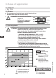
4.5 Laying suction and pressure lines
4| Compressor assembly
4.4 Pipes
Pipes and system components must be clean and dry inside and free of scale, swarf and layers of
rust and phosphate. Only use air-tight parts.
Lay pipes correctly. Suitable vibration compensators must be provided to prevent pipes being
cracked and broken by severe vibrations.
Ensure a proper oil return.
Keep pressure losses to an absolute minimum.
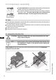
Fig. 12
Rigid
fixed point
As short as
possible
Aruleofthumb:Alwayslaytherstpipesectionstartingfromtheshut-offvalvedownwards
and parallel to the drive shaft.
ATTENTION Improperlyinstalledpipescancausecracksandtears,theresult
being a loss of refrigerant.
INFO Proper layout of the suction and discharge lines directly after
the compressor is integral to the system’s smooth running and
vibration behaviour.
1
2
3
4
5
6
7
8
9
10
11
12
13
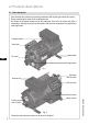
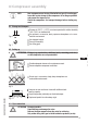
The pipe connections have graduated inside diameters so that pipes with
standart millimetre and inch dimensions can be used.
The connection diameters of the shut-off valves are rated for maximum
compressor output. Theactualrequiredpipecrosssectionmustbe
matched to the output. The same applies for non-return valves.
Fig. 11: graduated
internal diameter