
Manual

12
D
GB
F
E
96020-02.2015-DGbFEI
5| Electrical connection
5.1 Information for contactor and motor contactor selection
Allprotectiondevicesandswitchingormonitoringunitsmustbettedinaccordancewiththelocal
safetyregulationsandestablishedspecications(e.g.VDE)aswellaswiththemanufacturer’sinfor-
mation. Motor protection switches arerequired! Motor contactors, feed lines, fuses and motor
protection switches must be rated on the basis of the maximum working current (see name plate).
For motor protection use a current-dependent and time-delayed overload protection device for moni-
toring all three phases. Set the overload protection device so that it must be actuated within 2 hours,
if there is 1.2 times the max. working current.
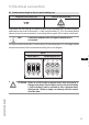
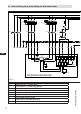
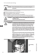
INFO
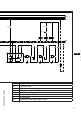
Connect the compressor motor in accordance with the circuit diagram
(see inside of terminal box).
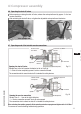
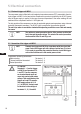
Use suitable cable entry point of the correct protection type (see
name plate) for routing cables into the terminal box. Insert the strain
reliefs and prevent chafe marks on the cables.
Comparethevoltageandfrequencyvalueswiththedataforthe
mains power supply.
Only connect the motor if these values are the same.
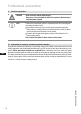
DANGER Riskofelectricshock!Highvoltage!
Onlycarryoutworkwhentheelectricalsystemisdisconnected
from the power supply!
5 Electrical connection